A new bridge which has just been completed in Japan is the first extradosed bridge in the world to incorporate butterfly webs. The original design was adapted by the contractor to enable it to be built much faster, to reduce the weight of the superstructure and to improve its seismic response.
Butterfly web technology was first developed by Sumitomo Mitsui Construction for use on a bridge built for the West Nippon Expressway Company in 2014 (Bd&e issue no 76) and has been used on four bridges since then.
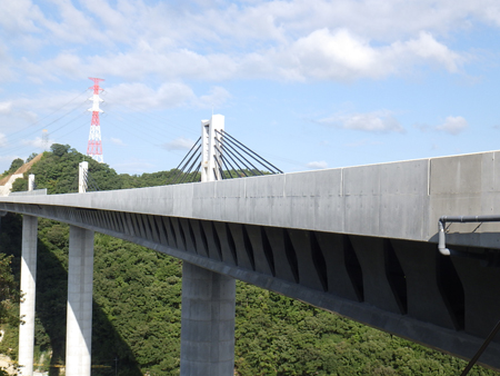
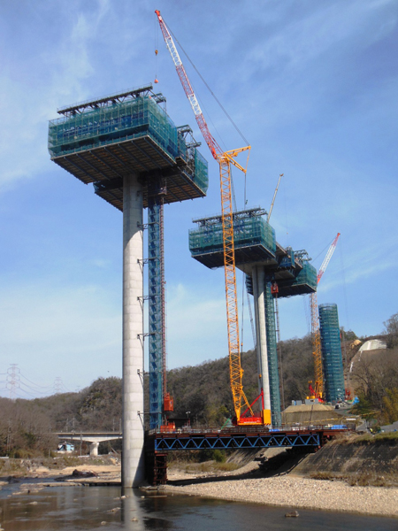
The Mukogawa Bridge is part of the Shin-Meishin Expressway which is currently under construction between Takatsuki junction and Kobe junction in Japan. This five-span continuous prestressed reinforced concrete rigid frame extradosed bridge is 442m long bridge and has spans of 100m.
Detailed design of the bridge was finalised with the intention of enhancing seismic resistance of the bridge as a whole, as well as minimising site labour to enable rapid and efficient construction. This was carried out by means of a number of adaptations to the design and construction procedures, introduction of custom-designed elements, and use of new techniques to build the piers.
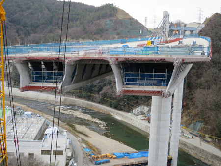
The structure has a uniform transverse section for the two carriageways, and while it has been built as a four-lane bridge, it is designed so that it can be expanded to accommodate six lanes in future. This will be achieved by installing 5.6m-wide cantilever decks on each side, supported by struts. The superstructure incorporates a ‘butterfly’ web combined with an extradosed structure; the web consists of butterfly-shaped concrete panels which replace the webs of a traditional prestressed concrete box girder.
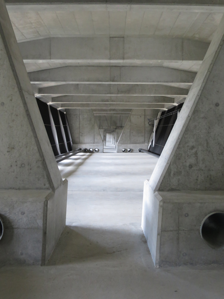
These panels are precast components, which are factory-fabricated using high strength fibre-reinforced concrete with a design strength of 80MPa. No reinforcing steel is used, which allows the web to be kept as thin as 150mm throughout the whole bridge, thereby reducing the weight.
The girder had to be kept a constant 4m height throughout the bridge due to dimensional restrictions on the transport of the webs. In order to achieve constant girder heights across the 100m spans, the extradosed structure was employed to stiffen the butterfly web structure using diagonal tendons at the pier head areas.
To address the significantly large shear forces generated around the supports, external tendons (12S15.7) and extradosed cables (19S15.7) were provided near the pier heads for the additional shear-carrying capacity. For the ease of future width expansion, the extradosed cables were arranged on the median strip in a single plane arrangement. The use of butterfly webs reduced the total number of elements required for construction, and hence shortened the construction period.
Using the extradosed structure with a constant girder height, combined with the butterfly webs, enabled the weight of superstructure to be reduced by about 20% from the basic design which is conventional box girder, enabling a consequent reduction in seismic forces.
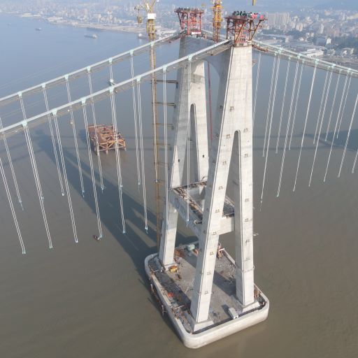
The pier which is located in the middle of the river was designed with a cylindrical hollow cross-section of 5m diamater in consideration of the obstruction ratio of the pier width to the channel width. Other piers were originally planned to be square hollow cross-sections ranging from 6.5m to 7m. Pier heights range from 81.2m to 54.2m, the tallest being the pier in the middle of the river.
But concerns were raised about the high rigidity of the square cross-section piers, which it was felt might cause the seismic force to be localised on the shortest pier. During the detailed design these were changed to a 5.5m-diameter hollow cylinder to reduce their rigidity and equalise the rigidity levels between all piers.
With this change in design, seismic force was expected to be distributed properly and also reduced significantly by the extended natural periods. Adequate bearing capacity was ensured by using high-strength steel for the longitudinal reinforcement, combined with 40N/mm2 or 50N/mm2 strength concrete for the piers. The total weight of superstructure and substructure in the detailed design was about 35% less than in the basic plan.
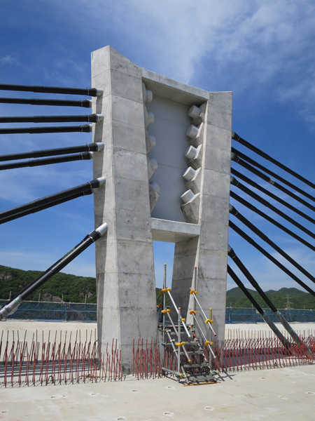
The bridge had to be designed to allow for future widening, in addition to which, it was difficult to meet the specified minimum radius of curvature by using a saddle anchorage for the extradosed cables which were to be placed at a maximum angle of 45°. Although it was decided to use single-plane separate anchorages at the centre of the cross-section, there was not sufficient space to anchor the diagonal tendons inside the tower using a conventional anchorage of steel or concrete.
The tower width was limited to just 1.35m, which was the width of the median strip. The solution was to develop a new, separate anchorage structure using a single steel plate and two concrete columns to fit within the restricted dimension. The steel plate in this anchorage structure is connected to the concrete using dowel reinforcement.
Since there was a concern about concrete filling the dowel holes in the 100mm-thick steel plate, the joint was fixed in advance using resin fill with the steel bars inserted in the holes. The concrete columns in which the extradosed cables are anchored are subjected to axial deformation due to the vertical component of force and horizontal deformation due to the horizontal component of force.
The steel plate embedded in the concrete columns resists the horizontal deformation through the joints and carries horizontal loads applied to both sides of it. The steel plate is divided vertically into three unconnected parts which are separated by 5mm gaps to prevent vertical loads being transmitted between them. Hence loads are distributed between the concrete columns, which carry vertical loads, and the steel plate which carries horizontal loads within the structure. The load transmission mechanism and intensity of stress were confirmed by a 3D finite element model analysis with gaps made in the steel plate. Furthermore, a load test using a full-scale model was carried out to verify the consistency of the analysis results in terms of bearing capacity and various phenomena.
The externally exposed steel plate and tendon anchor grout caps are spray-coated with aluminium-magnesium alloy for corrosion protection. The tall piers were constructed using prefabricated half-precast components, in a technique developed by Sumitomo Mitsui Construction, intended to improve earthquake resistance and enable rapid construction. Hoops and intermediate ties were embedded in the half-precast components during the fabrication for reduced assembly work at site. The half-precast components had a semi-cylindrical shape and were 2m high, in consideration of restrictions during transport and the capacity of cranes.
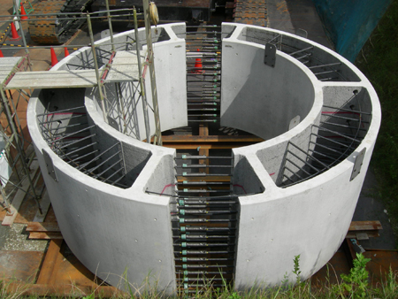
This special technique enables rapid construction by reducing the amount of reinforcement fixing and formwork assembly work required at site. The half-precast components are fabricated at a factory and brought to the site where they are installed by crane onto ready-fixed longitudinal reinforcement has already been placed. The minimum formwork that is required between the half-precast components is assembled, and the pier is completed by placing the filler concrete. In this project the sequence of scaffold assembly, assembly of the 12m-long longitudinal reinforcement, installation of the half-precast components, assembly of formwork and placement of filler concrete was carried out in cycles.
Filler concrete was placed for every three rings of the half-precast components which were about 6m high in total. Use of this method almost doubled the speed of construction compared to conventional cast in situ methods.
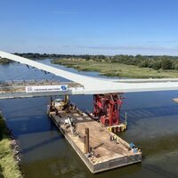
Complex work is usually required to form the webs of a prestressed concrete box girder; in this case, use of prefabricated butterfly webs led to a significant reduction in labour. With the main girder weight already reduced by the butterfly web box girder structure, it was possible to make the segment length a constant 6m. The segment length for cantilever erection is determined by the capacity of form traveller and is usually about 3m at the pier head, where the girder is deep or members are thick and about 4m between the piers in an ordinary prestressed concrete box girder.
Using this structure, the total number of segments in the bridge was almost halved from 101 in the basic design to just 54, and clearly this had a significant impact on the time needed for construction. As the girder is 24m wide, it protrudes a considerable distance from the 5m-diameter cylindrical piers in the transverse direction. There were concerns that such a structure might have an increased erection cost and also that safety might be impacted. Working at height was a potential issue, as was the need for a large-scale conventional scaffolding system with brackets of up to 15m installed in a radial shape.
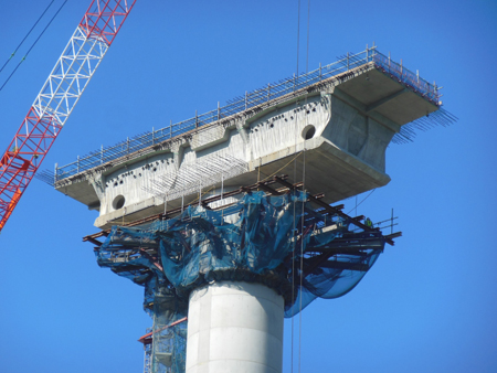
A new method was developed for the pier head construction to minimise the bracket scaffolding and improve safety. The new pier head construction method used precast segments for the cross-beam in part and substituted them for formwork scaffolding which could carry the loads of other segments to follow during the erection.
Bracket scaffolding was simplified by making it carry only loads of the column top. The precast segments to be erected in the transverse direction were designed with a unit weight of about 150kN and a unit length of 800mm to 900mm in consideration of the capacity of the lifting crane. The use of this method reduced the size of the bracket scaffolding to one third of the initial plan, successfully reducing the erection cost and improving the safety.
Construction of the Mukogawa Bridge Project started in 2011 and was completed in February this year, with opening scheduled for 2018. The design and construction were very complicated but construction was carried out as intended although some minor changes were made on the site. However, the construction was carried out as specified in the detailed design without any accidents and using an efficient and rapid method which enables significant reduction in labour. The structure has excellent durability and the openings created by the butterfly webs provide easy access into the box girder for inspection, making a great contribution to the ease of maintenance.
Owner: West Nippon Expressway Company
Designer: Sumitomo Mitsui Construction
Contractor: Sumitomo Mitsui Construction
Main subcontractor: Sumitomo Steel Wire Corporation
Akio Kasuga is chief technlogy officer of Sumitomo Mitsui Construction