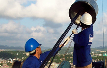
Japan is one of the most seismically active countries in the world and has suffered significant damage from earthquakes in the past. While the largest ever recorded was the 9 magnitude Great East Japan Earthquake of 2011, the most significant turning point for the country’s seismic code and bridge retrofitting programme was the 6.5 magnitude 1995 Great Hanshin Earthquake, with both events spurring initiatives aimed at preparing for – and taking countermeasures against – unprecedented tremors and tsunamis.
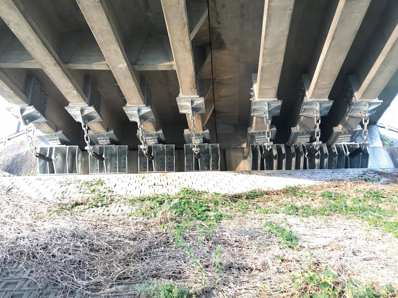 Nagatsuka Bridge was retrofitted with forty-two shearing stoppers and restraining chains (Sho-Bond Corporation)
A recent example is Shizuoka Prefecture’s Action programme for earthquake and tsunami countermeasures, which has involved retrofitting bridges to resist large Level 2 earthquakes. These events are extremely rare during the design service life of a bridge but are considered to have a significant impact. In Japan, small to medium earthquakes, which occur often during the service life of bridges, are classed as Level 1. Bearings which are resistant to Level 1 seismic motion are known as Type A. Bearings resistant to Level 2 seismic motion are known as Type B, and include lead core rubber bearings and robust steel bearings.
One of Shizuoka Prefecture’s crossings, Nagatsuka Bridge, is on a critical route under its action plan and links the important arterial road National Route 414 to Nirayama Railway Station. Built in 1961, the 91m-long simply supported concrete girder bridge has three spans comprising precast post-tensioned simple concrete T-girders. In 1984, three more T-girders were added to increase the structure’s width to 9.75m.
The bridge possesses 42 steel Type A bearings, and following analysis using the latest Japanese seismic standards, the installation of devices to supplement the bearings was recommended. This is because replacing the Type A bearings for Type B was challenging due to the limited space available between the T-girders and seat, at roughly 75mm. A Japanese construction company specialising in structural repair and reinforcement, Sho-Bond was selected as principal contractor for the retrofit project.
Where upgrading to Type B bearings is unfeasible, the need for bearing-supplement devices has been highlighted by major earthquakes in the past, which showed that even when unseating was prevented, the destruction of existing bearings and girder displacement caused major problems by disrupting important travel lifelines. There have been cases in the country where girders have been horizontally displaced and/or vertically lifted in the absence of such devices, resulting in long repair times and difficulties securing the bridge’s post-earthquake functionality.
In the case of Nagatsuka Bridge, one issue identified with installing any bearing-supplement device was that the main girder near the existing bearings has a dense arrangement of rebar and steel wire strands, causing concern that drilling bolts through the web would cause damage to the reinforcement and cracks in the girder. Shearing stoppers were selected to address this issue because these restraining devices can be fitted by using special installation attachments and mortar, without drilling the main girder web. In the event of bearing failure during seismic shock, the stoppers resist excessive longitudinal, transversal and lifting movements of the girder.
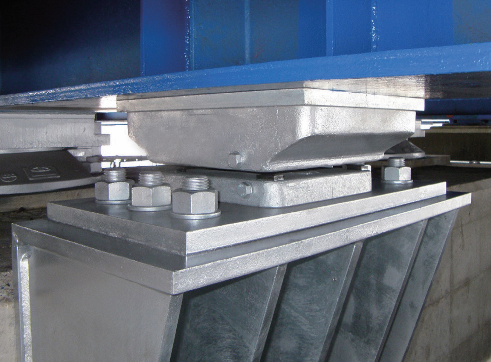 Brackets fixed to the substructure accommodate the shearing stoppers (Sho-Bond Corporation)
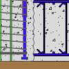
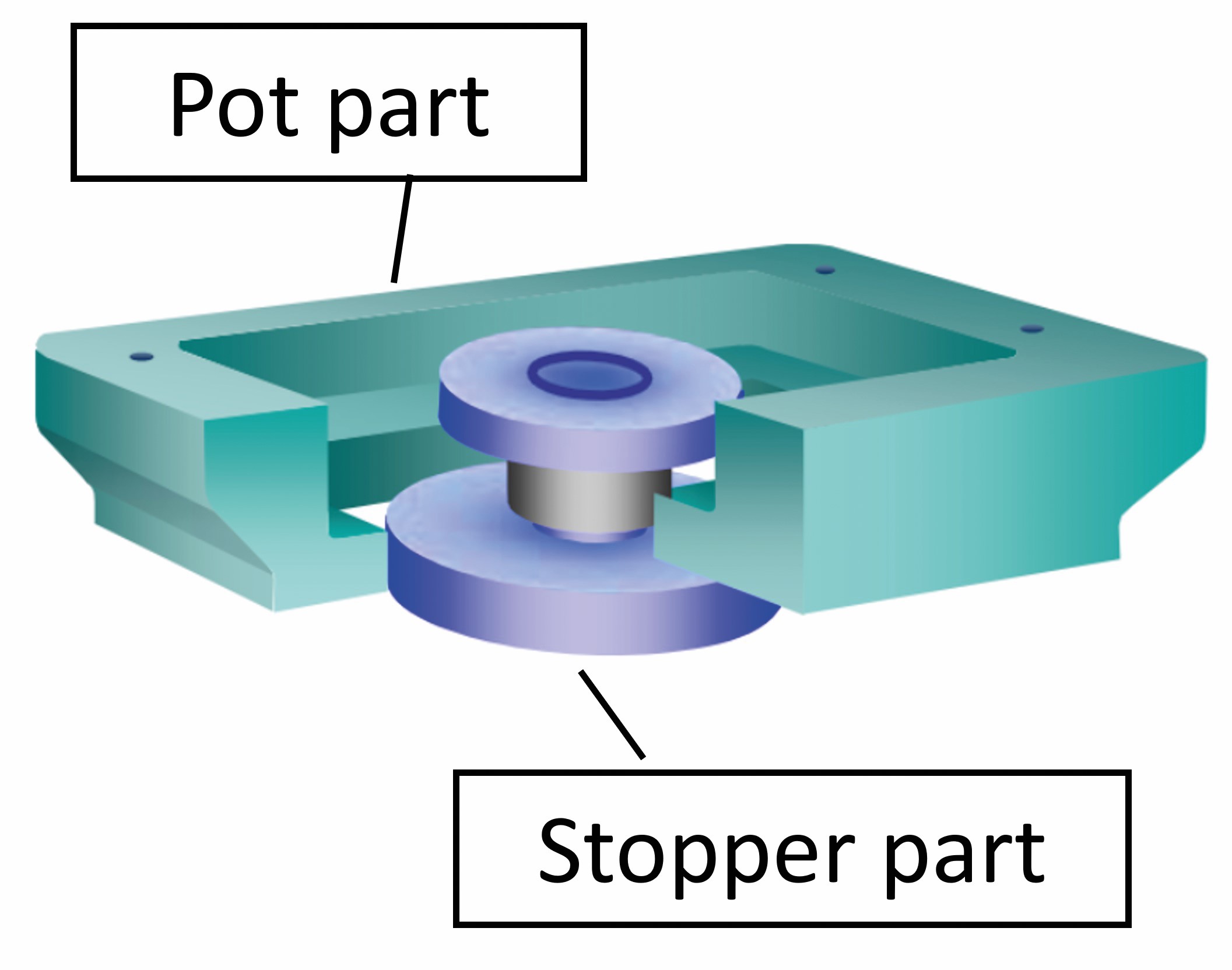
The device itself is divided into a pot section on the superstructure side and a stopper part on the substructure side. The pot part is fixed to the superstructure and the stopper is fixed to the substructure with bolts and anchor bolts. A gap exists between the pot section and the substructure, meaning the superstructure dead load is not applied to the stopper. The pot section can follow any movement and rotation of the superstructure caused by changes in temperature and live loads, and if the bearing fails, the device resists excessive movement of the girder as the pot part hits the stopper.
One major benefit is that unlike a conventional shear key, the shearing stopper secures a space around the bearing, making it is easy to remove and re-install the device. This facilitates easy access to bridge bearings for daily maintenance and regular inspections and makes it possible to inspect the bearings immediately after an earthquake, as well as replace failed bearings.
Some 28,000 shearing stoppers have been installed in Japan over the past 15 years, with the design force calculated as: seismic force to restrain times design horizontal seismic coefficient (Level 2) divided by number of bearings per bearing line. In the case of this bridge, the dead load is 1,300-1,600kN with three to four bearings per bearing line. The seismic force to sustain was determined at 2,600kN-3,100kN (longitudinal, fixed); 1,300-1,500kN (longitudinal, movable); and 1,300-1,600kN (transverse). The design horizontal seismic coefficient for a Level 2 event was calculated at 0.67-0.89.
Accordingly, the design force for the shearing stoppers was calculated at 260-810kN, depending on the specific installation location. A total of 42 shearing stoppers of six types have been installed to sustain 315kN- 860kN. All the stoppers used were off-the-shelf devices.
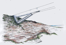
In tandem with the shearing stoppers, the bridge has also been equipped with unseating prevention devices known as restraining chains. These connect the main girder of the superstructure with the substructure and act as a fail-safe device to prevent unseating. The chain can not only alleviate the impact of the main seismic motion caused by an earthquake, but multiple seismic motions. A so-called shockless chain system is used to alleviate impact, which comprises rubber used for marine fenders moulded around a section of the chain.
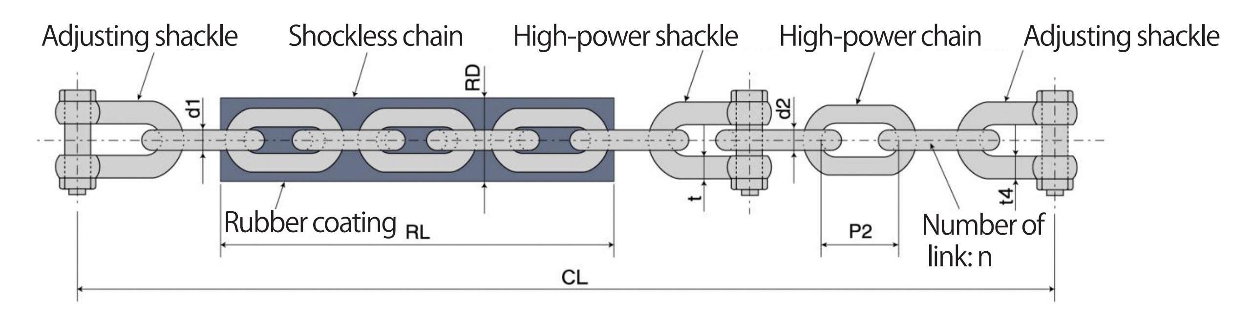 A restraining chain includes a moulded rubber section to alleviate multiple impacts
Besides the restraining chains, other options to prevent unseating, such as connecting adjacent girders with steel wire strands, were considered. However, this approach would have required reinforcing the transverse girder due to its lack of strength capacity. Other options were ruled out due to increased construction time and costs.
Regarding installation, since tensile forces in the downward direction of the main girder would be generated in the event of an earthquake, the superstructure bracket was fixed using bolts that penetrate the main girder web. Rather than using percussion drilling, waterjet cutting was adopted to avoid negative effects on the main girder. Meanwhile, the substructure brackets were used to install both the shearing stoppers and restraining chains to save time and costs: the chain was connected to the vertical face of the bracket and the stopper was installed on top.
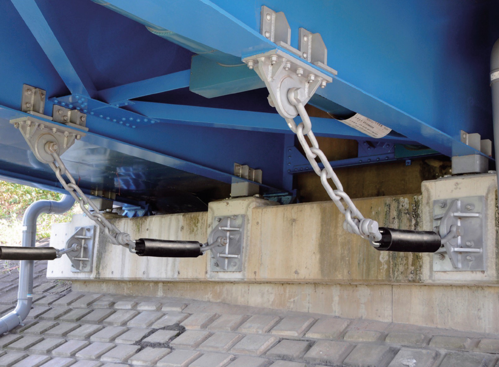 The restraining chains connect the main girder of the superstructure with the substructure and act as a fail-safe device to prevent unseating (Sho-Bond Corporation)
The design force of a restraining chain is calculated as 1.5 times dead load divided by number of bearings per bearing line. In the case of this bridge, the seismic force the chain has to sustain is 563-700kN, depending on the specific installation location. A total of 42 restraining chains of two types (615kN and 825kN) were deployed to sustain the calculated forces above.
The retrofit project was undertaken between October 2020 and May 2022.