A new high-speed rail viaduct at a site in northwest Spain is due to be finished later this year, report Francisco Millanes Mato, Miguel Ortega Cornejo, and Luis Matute Rubio
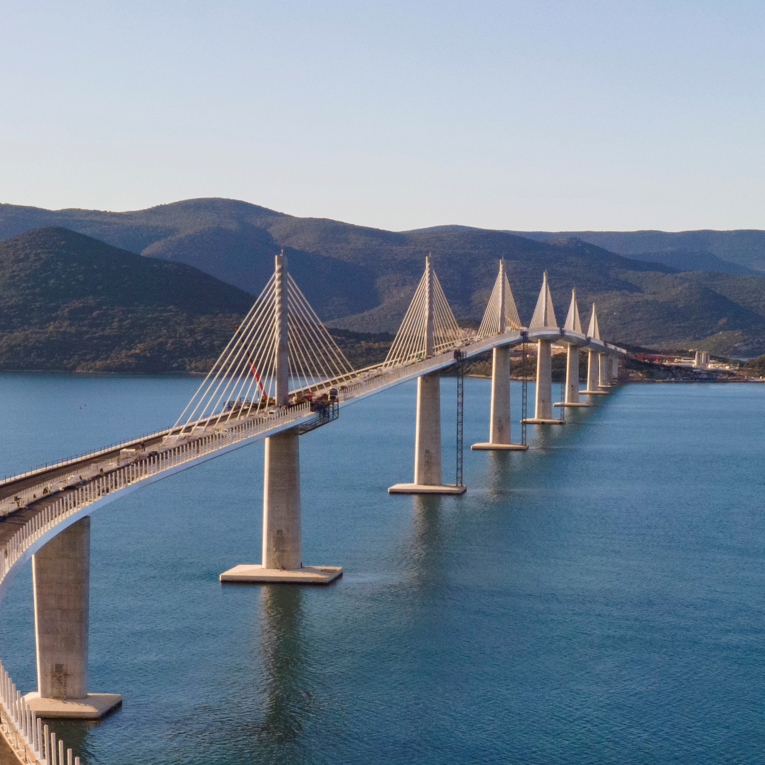
A composite viaduct which is currently under construction over the River Ulla in Galicia in Spain, will carry high speed trains on the Atlantic line between A Coruña and Pontevedra. The bridge is located close to the estuary of the river, on the Atlantic coast and in a landscape of outstanding natural beauty with tough environmental constraints.
Its design was the subject of a competition between a number of Spanish structural engineering firms, and the winning solution is due to be completed this year. The design selected is a 1.6km-long viaduct with a main span of 240m flanked by spans of 225m on each side. According to its designers, this makes it some 20% longer than the main span of the current world record holder for this type of high-speed rail structure, the Nantenbach Bridge in Germany which has a central span of 208m.
The Railway Division of the Spanish Ministry of Public Works invited six highly-regarded Spanish bridge specialists to a limited tender, with no reference design. Each engineer was given the freedom to propose the solution they felt best fulfilled the main specifications. A number of tough criteria were placed on the design of the structure, the first being the need for serious consideration of its aesthetic qualities and the integration of the viaduct into the landscape.
The number of piers in the watercourse had to be minimised to reduce the impact on the marshes and riverbanks of the River Ulla, while still keeping in mind the limitations of high speed rail bridges. The construction procedures, in particular for erection of the main spans, had to be as independent of the watercourse as possible, to avoid environmental damage.
Creating visual transparency and minimising the structure’s interference with the surrounding landscape were also key considerations. These factors contributed to engineering consultant Ideam’s choice of a composite steel-concrete haunched truss, with double composite action at the hogging zones next to the piers.
The bridge has three main spans; a central 240m-long span flanked by a 225m-long span on each side, six 120m-long approach spans, two 80m-long spans and a 50m span making up a total length of 1.62km. The superstructure was designed as a variable-depth truss over the five main spans, with its depth ranging from 8.5m to 17.3m; over the approach spans the truss has a constant depth of 8.5m.
The four central piers are specially designed with elegant, architectural shapes, and are longitudinally connected to the truss deck. This structural arrangement creates longitudinal frames which provide the three main spans with sufficient stiffness to withstand the strains from loads acting on alternate spans and keep within the stringent deformation limitations required for high speed railway bridges.
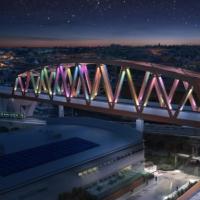
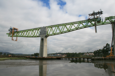
Special emphasis was placed on the integration of shapes and geometry between the concrete piers and the steel truss of the deck. The smooth depth variation along the deck, with its upward curves, creates a serene aesthetic over the width of the river, with the colour combination of grey concrete and light green truss adding to this effect.
The cross-sections of both the upper and the lower chords of the steel truss are 800mm wide, parallelogram-shaped girders; the upper chord is 1m deep while the lower chord is 1.2m deep. Diagonal members are also parallelogram-shaped, with main dimensions of 800mm wide and 1m deep.
The upper chords have a box beam welded to the upper flanges and embedded in the concrete slab to create the connection, allowing shear to be transferred closer to the centre of gravity of the composite steel and concrete upper member and avoiding the appearance of local forces and moments in the upper joints.
The upper cast-in-place slab is made of C35/45 concrete and ranges from 460mm deep at the midpoint to 250mm at the edges. It is placed directly over the steel upper chord, configuring a composite steel and concrete cross-section structure. Along the hogging zones near the piers, a C50/60 concrete slab is connected to the bottom steel chords, allowing a double composite action strength mechanism.
On the sagging zones, the deck’s lower face will be created by the use of in situ concrete. Originally the lower concrete in these locations was designed as precast concrete slabs with no structural purpose, but in the end the contractor elected to change the precast slabs to in situ concrete with no connection to the steel chords, and longitudinally discontinuous every 16m with joints.
The four central piers of the bridge are monolithically connected to the deck, configuring a longitudinal frame which increases the stiffness of the structure and improves its behaviour as regards horizontal forces. The stiffness of these piers has been optimised in order to restrain deck rotations, control the deflection of the three main central spans, and reduce the bending moments that are transmitted to the foundations.
In this way, the piers that flank the 225m-long spans have been designed with two separate shafts from base to head, in order to avoid the excessive bending moments that arise from the imbalance from the presence of a 225m span next to a 120m span, as well as those produced by temperature and shrinkage displacements.
In both cases these moments are central than in the central piers since they are further from the neutral displacement point. The side span piers have a more conventional design with a hollow box girder cross-section which varies in depth both transversally and longitudinally.
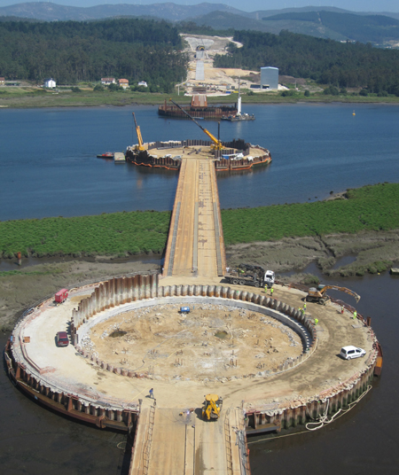
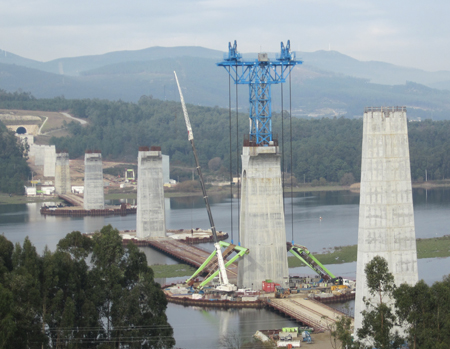
Pier foundations are supported by the existing granite substratum via a direct foundation; however on piers P5 and P6, the alluvial deposit thickness prevents the use of footings and has demanded the installation of deep foundations. The biggest of these is P6 which has a foundation of 56, 1.5m-diameter piles and a reinforced concrete pile cap of 34.5m by 30m by 5.5m. The construction method selected for the viaduct was also required to have the minimum impact on the river flora – any works that were needed in the river had to be temporary.
Three of the bridge piers are founded in the river and they were built within huge double-walled sheet piled cofferdams with a diameter of 68m, to allow them to be dewatered for construction of the piles and the pile caps. A temporary steel bridge was also built to provide access to these piers and this was supported on temporary driven piles installed at 6m intervals. Construction of this provisional access had to be carried out with care, to avoid any possible contamination of the river water, and any impact on protected local fauna. The use of these temporary bridges simplified the access to the work sites and avoided the need to use barges.
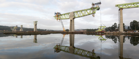
Once the foundations were completed, the piers were built with the aid of climbing formwork and when the shaft piers P5 to P8 was at full height, the pier-top ‘w’-shaped steel segments were assembled in a horizontal position at the base of the piers. After both side truss segments were finished, they were lifted and fixed into position over the piers.
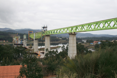
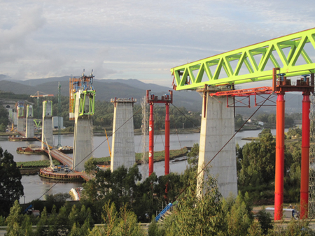
Each of these huge segments weighs around 375t, and they are 35m long and 17.5m deep. With the concrete element of the pier heads completed, the balanced cantilever method of construction has been chosen for erection of the variable-depth steel truss of the five central spans, from the pier-top section to the closing segment at mid-span.
This method enables the deck erection to be carried out without impacting on the surrounding marshes and the river. Welding of the different elements that make up a single 15m-long segment – nodes, chords, diagonals and bracings – is carried out at one of the three steel workshops located near the bank of the river.
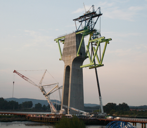
Once each segment is assembled it is transported to the base of the appropriate pier by use of a self-propelled modular transporter with multiple axes. At the pier base, a gantry crane is used to lift the module off the trailer, move it to its final position on the span, and lift it to be welded in place. This procedure began in July 2013 and is due to be finished later this year.
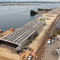
The constant-depth trusses on the side spans are being built by different methods due to the different conditions at ground level on each side of the river. The south side crosses several local roads and a railway, so construction was carried out by the use of launching in three different phases.
However there is not enough free space at the end of the bridge to create a conventional launching yard due to the presence of a tunnel, so the yard was built on temporary supports between the abutment A1 and the first pier. Each 120m-long span was assembled in the launching yard by welding the segments over temporary supports, and once finished it was launched.
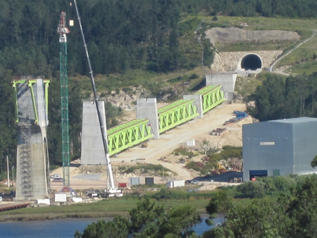
The second launching operation saw the movement of two complete spans each 120m long, and finally the lateral side spans which are 80m and 50m long, were welded on site over the temporary props by erecting each segment with the use of cranes. The four lateral approach spans near abutment A1 were completed last year.
On the opposite bank, the approach spans were not subject to the same restrictions since there are no ground-level obstructions, hence a procedure for lifting full-length spans was designed. These spans are assembled by being welded together on the ground at the site, and the complete spans are then lifted vertically, and welded to the previous one making them continuous.
The approximate weight of the 120m-long spans is 900t and the 80m span is 465t. The lifting of the full-length spans is being carried out using four jacks each with a capacity of 500t. The jacks are placed on top of an auxiliary structure which is connected to the pier-top segment.
Once the assembly of the steelwork is completed the lower slab will be poured using movable formwork. The following stage will be the simultaneous and controlled downward displacement of the deck by 250mm at piers P4 and P9, so as to reduce the bending moments of the rest of the dead loads and live loads on piers P-5 and P-8 produced by the imbalance of the span lengths.
The upper concrete slab will be poured on the precast concrete deck units, designed with the total width of the deck. The bridge is due to be finished by autumn this year, at which time it will become the world record holder for this type of bridge.
Francisco Millanes Mato is president, Miguel Ortega Cornejo is engineering director and Luis Matute Rubio is general manager at Ideam
Client: Railway Division of Spanish Ministry of Public Works
Consultant: Ideam
Contractor: UTE río Ulla (Dragados-Tecsa)
Fabrication: Joama & Ascamón, Emesa, Dizmar, Martifer
Heavy moving: ALE