With fabrication of new deck units set to start next month (December) and site work scheduled to begin in the spring of 2015, the contract to replace the truss deck of Canada’s Angus Macdonald Bridge is now getting up to speed. It is only the second time in the world that a full-scale replacement of a suspension bridge deck has been carried out in this way – with deck units replaced during overnight closures and the bridge reopened to traffic in the morning.
However, some of the conditions facing engineers on this project differ significantly to those encountered on the previous project on Lions’ Gate Bridge in Vancouver which was completed in 2002.
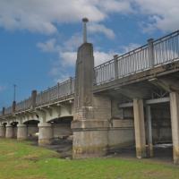
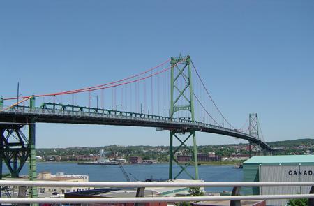
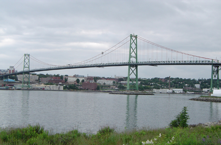
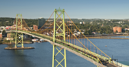
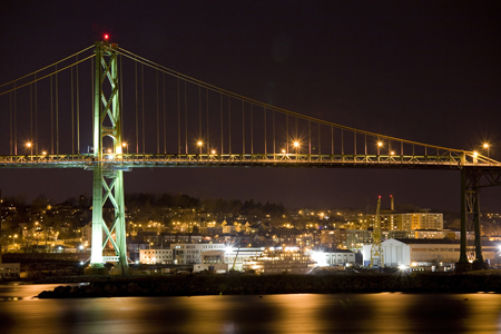
The Macdonald Bridge was opened in 1955 and connects Dartmouth with downtown Halifax in Nova Scotia; the 1.3km-long link includes a 762m-long suspension bridge and approach structures. The existing deck system is deteriorating in three ways, the most urgent being that water penetrating the concrete-filled, welded steel grid has caused corrosion between the bottom of the grid and the tops of the supporting stringers, resulting in the deck becoming separated from the stringers.
This creates an undulating roadway surface which is unpleasant to drive on and requires constant and increasingly onerous maintenance. The second aspect is the thin asphalt running surface which wears continually in the traffic wheelpaths, exposing the upper steel surface of the T-grid and reducing the skid resistance of the deck.Thirdly, the deck stiffening truss, a through truss, is formed of riveted, built-up steel members. These have large exposed areas which require labour-intensive maintenance painting.
The owner, Halifax Harbour Bridges, was keen to keep the bridge open during the day and carry out the replacement of the deck at night because of the impact that a full closure would have had on the area’s transportation network. The Macdonald is one of two suspension bridges over Halifax Harbour owned by HHB; the other is the A Murray MacKay Bridge, a four-lane bridge which opened in 1970.
Between them the two bridges carry 34 million crossings a year: 60% on the MacKay and 40% on the Macdonald. The new deck will be orthotropic with a 14mm-thick deck plate in the carriageway with 300mm-wide longitudinal trough stiffeners at 600mm centres, and a 10mm-thick deck for the footway and cycle track. The new top and bottom chords are designed as closed sections, and are tucked under the deck plate to protect them from rain and deicing salt. The deck plate then forms the top plate of the top chord, which is an efficient structural arrangement.
Loads on traffic barriers are resisted by specially-shaped longitudinal trough stiffeners under the deck plate acting in torsion Outer vertical plates of the bottom chord box extend above the top plates, providing a rail for the support of under-deck maintenance travellers.
The fences of the outer footway and bikeway are raked inwards to deter climbing and the system is also designed so that a 610mm-diameter water pipe can be supported beneath the deck on the lateral bracing system.
Finally, the surface area to be painted is less than half that of the original. The work will be carried out in a similar way to the deck replacement at the Lions' Gate Bridge in Vancouver. Work will begin on the Dartmouth side at the cable-bent and progress towards to the Halifax main tower.
Deck segments 20m long will be supported from above by a movable erection gantry so they can be detached from the existing deck system by cutting the top and bottom chords and diagonals and then be lowered onto barges below by strand jacks.
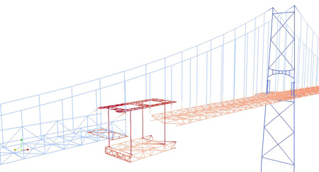
The new factory-fabricated deck segments will then be raised up to the deck level using the same strand jacks, and connected on one end to the adjacent existing deck segment via a temporary load transfer connection, and on the other by bolting to the most recently-installed new deck segment. In order to release the loads in the new and old deck segments and align them before making the connections, the existing hangers must be shortened or elongated in a prescribed sequence to transfer loads from the deck to the main cable.
Adjustable hanger extensions will be used during this process to adjust the distribution of the forces to the main cable and to the stiffening trusses to ensure that no component is overloaded at any time. The existing deck has a cantilevered footway and cycle path, and these components must be removed before the deck segment replacement can begin.
Since the new deck segments will be lighter, they will have to be temporarily ballasted to maintain the geometry of the old deck until the new deck is fully installed. Not all of the deck can be replaced using this procedure – the section of deck between the main tower and the cable-bent on the Halifax side of the bridge crosses over office buildings occupied by the Canadian Department of National Defence. Lifting from below is not possible here, so instead, segments will be brought in sideways by truck from the Dartmouth end of the bridge over the newly-installed deck.
These segments – 10m long rather than the typical 20m – will be lifted off the truck, rotated by 90° and lowered into place. Although the project is intended to follow the general concept used on Lions’ Gate Bridge, it is more complex in three significant ways.
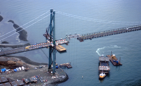
Work being carried out on the Lions' Gate Bridge in Vancouver
Wind effects are much higher on the Macdonald Bridge; erection analysis is being performed by the owner's engineer, not the contractor; the main span of the bridge is to be raised to increase shipping clearance. Wind loading at the site is considerable since Halifax is situated where weather systems collide, creating high winds. In the past, hurricane winds from Atlantic storms have caused major damage in the city.
A site-specific wind climate study, which included a hurricane study, was carried out by RWDI to determine maximum expected winds at the bridge site. Based on the climate study, the mean hourly design wind speed at deck level is 36.1m/s, while the deck must remain aerodynamically stable for 10-minute wind speeds of 49.2m/s at deck level.
Compared with the design wind speeds at Lions’ Gate Bridge, this represents an increase of approximately 44% in the structural forces due to wind loading. During construction, the criteria are relaxed slightly, and the bridge must withstand winds of 30.5m/s and remain aerodynamically stable for wind speeds of 44m/s. In order to address the more onerous loading conditions due to the wind, the temporary deck connection was strengthened to provide a rigid connection between the old and new decks, rather than flexible as was used at the Lions’ Gate Bridge.
Although the design of the truss is similar to that used at the Lions’ Gate Bridge, wind loading becomes the governing case. Lower tower splices will be strengthened, as will the cable bents, with some bracing members replaced. The cable bent foundation on the Halifax side will be strengthened to resist combined dead, temperature and wind loads, and larger expansion joints are specified to accommodate larger wind-induced movements.
Dynamic wind-structure interaction is of particular importance on long, flexible structures such as suspension bridges, and for this project, three specific circumstances were investigated; the wind on the existing bridge; the wind on the partially-completed bridge, in particular for design of the temporary deck connection; and the full design wind, from the wind climate study results, on the completed bridge.
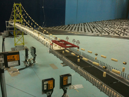
Extensive physical modelling in the wind tunnel was used by RWDI to address the concerns related to the bridge design and erection sequence analysis. Several models of the existing and new bridges were built in order to confirm the aerodynamic stability of the bridge both in its completed state and during erection. They were also used to measure aerodynamic coefficients which are used as input to the dynamic buffeting analysis.
A sectional model of the existing deck; sectional model of the new deck; aeroelastic model in the final condition and three aeroelastic models during erection were built for testing; these models consisted of the partially-erected new deck and the existing deck with connections at midspan and in the sidespan.
This wind tunnel testing confirmed that the bridge deck is aerodynamically stable during the erection sequence and in its final condition. In addition to the physical testing in the wind tunnel, several dynamic buffeting analyses of the bridge in its various configurations were performed to calculate the force effects in the bridge structure.
These were then used for final design of the new bridge elements and checking of the elements that will remain. Buffeting analysis of the bridge in its existing and final condition, along with the six buffeting analysis runs for the erection stages, were used to investigate the various wind loads on the bridge throughout its transformation.
Design of the main erection equipment has been carried out by Buckland & Taylor, assisted by local firm Harbourside Engineering, on behalf of the owner. On Lions' Gate Bridge this task was carried out in the traditional way by the contractor.
This significant change in project delivery was chosen to lessen overall project risk and speed up the process by performing most of the analysis of the erection sequence ahead of the contract tender. Having the owner’s engineer carry out the erection analysis has saved an estimated year or more on the construction schedule. Buckland & Taylor has spent two years automating the creation of the more than 5,000 computer models that represent every change to the structure as the bridge is altered, a task that would be too complex for a contractor to carry out in the time available for construction.
This decision also reduced uncertainty during the bidding process. There is still a lot of temporary works for the contractor to design, but the key pieces of equipment were designed by the owner’s engineer. The erection analysis has been independently checked by Ammann & Whitney.
The third difference from the Lions’ Gate Bridge project is that once all the new deck segments have been installed, the deck will be raised by 2.9m at mid-span to increase shipping clearance. This movement will provide an extra 2.1m height at the edge of a 110m-wide navigation zone. Halifax is the closest port to Europe on the North American mainland and ships have to pass under the Macdonald Bridge to reach the inner harbour.
Increasing the clearance below the bridge deck will allow the largest post-Panamax vessels through. Once all the deck segments have been installed, the deck will be raised by jacking at each vertical hanger. To maintain a smooth vertical curve, the deck will also be raised at the towers and over part of each side span.
This procedure will induce stresses in the deck, particularly compression stresses in the bottom chords of the deck trusses, which must be combined with those caused by vertical uplift and horizontal wind loads. Significant analytical effort was used in designing the structure to accommodate this critical load combination. Some additional topics were investigated as part of this project.
For example, the engineer suspected that the Canadian Highway Bridge Design Code may overestimate the required movement of the expansion joints on this bridge, because live load, applied vertically, can cause longitudinal movement of the deck and the code was most likely not written for this condition. To resolve this, a one-year in situ displacement measurement programme was instituted by Halifax Harbour Bridges to correlate measured displacements with meteorological and typical traffic conditions.
Analysis of the data showed that the code does indeed overestimate the longitudinal movements caused by traffic. Secondly, surveying a large suspension bridge is challenging because the bridge is constantly moving. While is it possible to close the bridge to traffic, special surveying techniques must be used to capture the deck and tower positions when surveyed and to temperature-correct the recorded data to determine the bridge position at a reference temperature.
The challenge was enhanced by having weeks on end with the weather either too foggy for surveying, or too windy for accurate instrumentation. Another aspect of the project is that a dehumidification system that is being installed to protect the main cables.
An inspection in 2010 found that the cables were in good condition, with little sign of corrosion, negligible material loss and galvanising substantially intact and few broken wires, but there was moisture inside the cables that would lead to long-term deterioration.
The dehumidification system will be installed after the deck is replaced but while there is still access for construction, in late 2016 or 2017. The contractor American Bridge Canada is now preparing detailed plans for the project, including safety, inspection, test and quality control plans, and submitting shop drawings. Steel is on order with fabrication trials being carried out, and full-scale fabrication expected to begin in December.
Site work will begin in March 2015, the first task being to reinforce the existing trusses so they are not overstressed during construction, and drain the water main, followed by removal of the footway and bike path in June. The first segment is expected to be replaced in late summer/early autumn 2015.
Keith Kirkwood is chief project manager, Dusan Radojevic is project technical director and Peter Buckland is project principal at Buckland & Taylor. Jon Eppell is senior bridge engineer at Halifax Harbour Bridges.