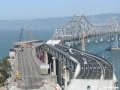
The Léon Blum Viaduct provides a new link across the Boivre River and the large railway station which runs along the valley bottom in the former industrial area of Poitiers. The project connects the historic city in the east with a new suburban landscape in the west and is on the same axis as the newly-built Théâtre Auditorium de Poitiers in the historic centre of the city, which is located in the west of France.
The new bridge replaces a former pedestrian bridge, and its incorporation of rapid transit bus lanes, with a bus stop actually on the bridge, is intended to improve the public transport network of the city, playing a strategic role in its development on a larger scale.
It is a composite structure with steel piers, steel truss superstructure and concrete deck, and it spans a total length of 310m over the river valley and railway lines. Its width, which varies from 14m to 20m, accommodates two lanes of rapid transit bus and two pedestrian footways of 3m width on each side of the deck.
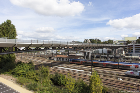
Simplicity and elegance were the key to properly integrating the new bridge into the surrounding cityscape. The structure has been sub-divided into spans of 81m to give it a regular, balanced appearance, and a minimum of materials was chosen to respond to the somewhat dissonant surroundings of the railway lines, river valley, carpark structures, and the historic city centre.
Light pigmented concrete and asphalt were used to reflect the native stone of the region with which many of the surrounding buildings are built. The bus stop on the bridge takes its design cues from the form of the bridge with the curvature of the station roofs echoing the curvature of the bridge deck soffit, to create a fully-cohesive design.
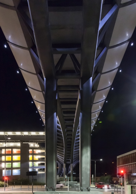
The design of the bridge was subject to some major considerations at the valley floor, in particular relating to the scale of the structure and its potential impact. It is necessarily a high bridge, up to 18m above the railway and the Boivre valley, and it also passes very close to a number of buildings and a parking garage, at approximately roof-top height.
Given these particular constraints, it was clear that the design of the underside of the structure was critical to the success of the project. To address this, the designers sought to create a ‘living arcade rooftop’ for the valley.
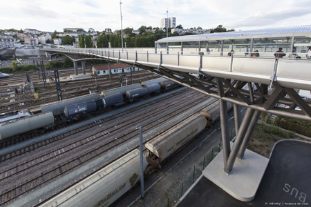
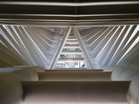
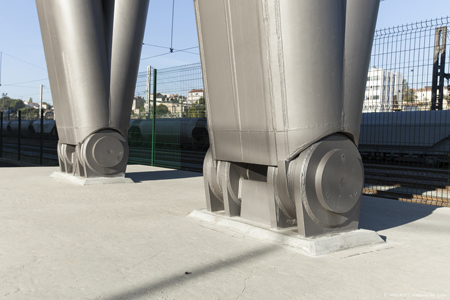
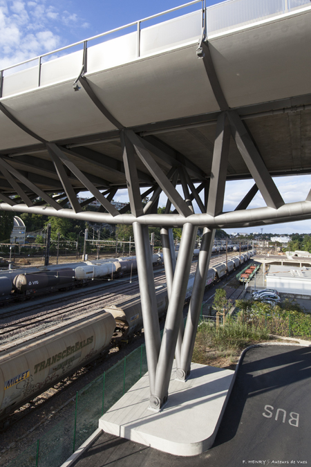
The steel semi-Vierendeel truss structure below the deck is intended to maximise the transparency of the bridge and reduce the scale of the structural components in response to their proximity to the user and the existing buildings. Pier footings are also articulated to minimise their impact on the valley floor.
Tubular steel truss piers spring from these discrete articulations to integrate into the truss girder and create a single unified form. With this approach, the area of the bridge most directly in contact with the town is freed from the kind of massive support commonly associated with this type of bridge.
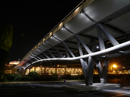
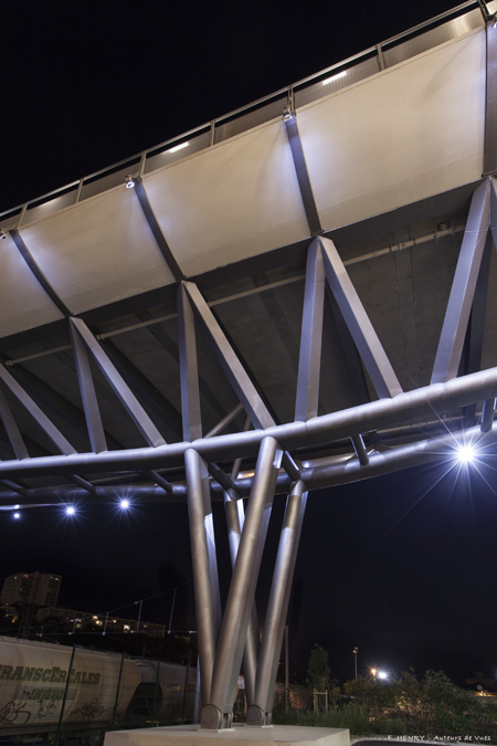
The intention is to integrate the bridge within its constrained urban condition. The lighting is designed to emphasise the horizontality and the slenderness of the viaduct. It does this by use of a linear and continuous display of significant architectural components – the bottom chord of the structure in particular – to reveal and emphasise its geometry.
The lighting scheme emphasises the materials and different surface aspects of the viaduct structure but not the lighting devices themselves, which are hidden within the structure itself. On the deck, the lighting is integrated directly into the kerbs and railings and illuminates the deck surface to provide sufficient lighting for the pavement. On the deck the only lighting masts are at the bus stop. Extensive studies carried out during the detailed design stage allowed the final design of the viaduct to remain true to the conceptual vision.
During this design process, the cross-sections of the structural elements were optimised and refined to emphasise the slenderness of the architectural composition. In order to minimise the cost and impact of the bridge, the structure was based on reliable erection techniques and construction processes.
This led to the design of a truss as ‘structural lace’ composed by a series of clearly organised, hierarchical structural components that provide an answer to the structural needs and generate an open filigree structure that blends in with the city’s fabric. The deck of the viaduct is a hybrid structure with a concrete slab and steel truss. Its depth and width vary geometrically and behave structurally as an open girder box with a maximum depth of 4m over the piers to 2m at mid-span.
The spacing of the lower chords varies in plan with a spacing of 4m above piers to 3m at mid-span. The piers of the viaduct are structurally fixed at the top and articulated at the base, with the continuous connection between the girder and piers creating a frame structure.
Expansion joints are provided at both abutments and the longitudinal braking and temperature forces are carried by bending in the rigid frame created from the girder and piers. The lower chords of the truss create a seamless and continuous curve with an oval form, the latter being fabricated from welded open H-sections with semi-circular bent plates welded between the flanges. The oval section has a constant depth of 660mm with a width of 1.26m.
The semi-Vierendeel structure of the truss increases the spacing between diagonal members while providing the required shear stiffness. The diagonal members are cruciform sections created from heavy welded plates that transfer bending moments between the lower and upper chord of the truss; these cruciform sections are enclosed by bent cover plates, creating an outer diamond-shaped form for these members.
The bridge deck is composite with the steel truss. Steel studs are welded to the upper longitudinal chord and transverse girders. The transverse beams are constructed using open welded H sections with depths that vary between 400mm and 600mm, however deeper sections of 845mm are required below the bus stops to accommodate the wider slab at this location.
The longitudinal members that make up the upper chords of the truss have a constant depth of 400mm and are also constructed from welded built-up H sections. Lateral edge units of prefabricated concrete cover the utilities and cabling which is incorporated in the deck. The underside of these units is aligned with the lower flange of the longitudinal member to create continuity with the steel structure below deck.
The viaduct is founded on poor quality Karstic ground, hence exploratory boreholes were needed at each foundation location to ensure no voids were present. Because the structure works as a frame, lateral forces must be resisted at the pier footings, the most significant of which is the foundation of the short end pier, given its rigidity in the system. Twelve drilled piles were required for this footing, while on the taller piers, six drilled piles were sufficient. As there are expansion joints at each abutment, the abutments are subjected to less loading and were founded on spread footings with integrated shear keys. The bridge crosses a total of 21 railway tracks carrying high speed and local trains, and this presented a significant constraint for the design, construction, and structure of the viaduct.
French national rail standards typically demand vertical catenary protection to a height of 2.5m above the walkway; this would have had an impact on the openness of the bridge deck and was a significant challenge to the intention to create an overlook on the bridge deck. The owner and design team raised the issue and were granted an exemption from the requirements based on the fact that the deck is already at a significant height above the rail yard.
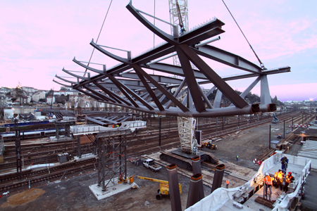
One pier foundation is located in the railway yard and heavy equipment could not be used to construct the drilled shafts for the foundation. A total of 56 vertical and inclined micro-piles were used instead and protection of the pier was provided by a shock-resistant concrete foundation pedestal. The bridge was originally conceived as a launched structure, but the national rail authority demanded that the construction procedure be modified with the structure lifted in place instead.
This required additional temporary supports so that the spans could be reduced to manageable weights for lifting. One temporary support foundation required a complete removal of the track and its subsequent reconstruction. Structural steel was fabricated by Cimolai in Italy with welding and pre-assembly for transport carried out at Zwahlen & Mayr in Switzerland.
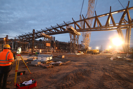
The steel elements were prefabricated to lengths of 15m and shipped to site by heavy transport. Once on site, the final assembly was welded to lengths of approximately 27m – and a maximum of 33m – and painted in controlled conditions before being prepared for lifting. Lifts were carried out during six-hour night-time rail possessions in coordination with the rail authority.
Once the steelwork was erected, the prefabricated deck slabs were placed on the steelwork, also during the possessions, and the joints concreted. Once the slabs were completed, the concrete shells were lifted in place and the utilities and conduit installed. Finally, bridge surfacing, painting, and electrical installations were completed.
Client: Grand Poitiers, Communauté d'Agglomération de Poitiers
Designer: RFR
Design-build joint venture: Vinci Construction France, GTM Bretagne, Freyssinet, RFR
Landscape architect: Michel Desvigne Paysagistes
Lighting designer: 8’18’’