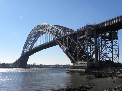
(Photo: Matthew Myerscough)
Bridge engineer Othmar Ammann designed the mighty Bayonne Bridge to accommodate a future increase in highway traffic – ironically it is the increase in vessel size that is driving the major structural intervention currently under way.
When Ammann drafted his original scheme, it was longest steel arch in the world, with a span of 504m between bearing centres. Crossing the Kill Van Kull, a narrow tidal strait between Staten Island in New York state, and Bayonne in New Jersey, the bridge opened to traffic in 1931. Since then, road users have occupied a 12m-wide carriageway on the bridge, despite the two arch trusses being spaced at 22.5m apart. This discrepancy was not the result of poor design; quite the opposite, as Ammann had future-proofed his bridge by providing space to widen the roadway to 20m if necessary. Yet despite his prudence, Ammann could never have predicted the massive size of the modern day container ships which pass under the bridge to reach the bustling ports of Elizabeth and Newark. Back in the 1930s, even the tallest vessels in the US Navy could fit easily beneath the highway deck, which is 46m above the water.
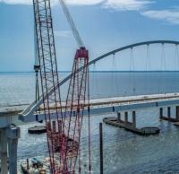
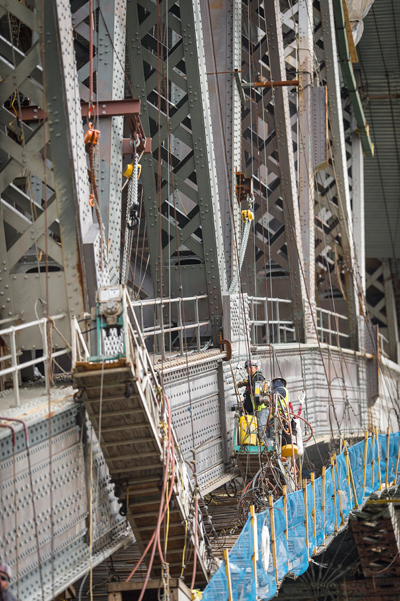
Construction of the new tower structure on the NJ side surrounds the existing tower. Note the difference in elevation between the existing roadway and the new roadway
In fact the comparative study for the first Bayonne Bridge identified three suitable structural types; arch, cantilever, and suspension bridge. Despite Ammann’s suspension bridge expertise, and high-profile projects such as the George Washington Bridge, a steel arch was selected to cross the Kill Van Kull. This was in part due to the presence of solid bedrock at a shallow depth beneath the water which was favourable for resisting the enormous thrust of the arch ribs. Furthermore, the greater stiffness offered by the arch was considered an advantage should the bridge deck be converted in future to include rapid transit tracks, which Amman’s design permitted as an alternative to increasing the roadway width.
Today Panamax ships – the maximum vessel size that can fit through the Panama Canal – have grown too big to reach the Elizabeth and Newark marine terminals. Combined, these ports handle up to US$200 billion of cargo each year and are some of the busiest on the east coast. A loss of trade due to bridge clearance limitations could be catastrophic for the region’s economy. With widening of the Panama Canal locks due to be complete next year, allowing through an even larger generation of post-Panamax ships, something had to be done.
Six years ago, the Port Authority of New York & New Jersey, which owns the Bayonne Bridge, commissioned a study into the feasibility of increasing the vertical navigation clearance of the existing structure. The total length of 2.126km the crossing includes two plate girder approach viaducts which bring the roadway up at a gradient of 4% to the steel arch. Over the central part of the crossing the bridge deck is suspended from the arch. The arch consists of two braced steel trusses which decrease in depth from 20.6m at the abutments to 11.4m at the crown. Parabolic chords define the shape of the trusses, which are divided into forty panels each 13.4m long. From the abutments, the roadway runs above the upper arch chords for the first two panels, at which point it passes through the arch and emerges on the underside of the sixth panel. The remaining 28 panels of deck in the middle of the span are suspended from the lower arch chords on galvanised wire rope hangers.
Consultant HDR carried out an evaluation of alternatives, which included 41 options based on three general schemes; raising the roadway within the arch, raising the arch by means of jacking, and constructing a new structure. The study identified and compared right-of-way constraints, environmental considerations, costs, construction feasibility and scheduling.
Raising the bridge roadway within the existing arch would require demolition of the original bridge roadway and construction of a new deck at a higher level. Three different levels for the new bridge deck were considered, providing either a 56.4m, 61m, or a 65.5m navigational clearance. Several common issues were considered for each option which included relocating the openings for the roadway in the upper and lower chords of the arch.
To jack the entire arch vertically, the existing abutments would have to be extended and strengthened with buttresses. Challenges associated with this scheme included substructure design, lifting procedure, structural steel design, and construction staging. A preliminary substructure analysis evaluated the stability of the bridge abutments with the arch in the new raised position.
The final scheme considered construction of a brand new bridge on separate alignments both east and west of the existing structure. Again concepts were developed for three vertical clearances, with options including a three-span cable-stayed bridge with a composite steel and concrete deck. A 488m-long main span flanked by two 200m-long approaches was established as the most suitable arrangement for any replacement bridge. Due to the stately and historic nature of the existing structure, which was designated a National Historic Civil Engineering Landmark in 1985, the arch would have been left in place with the road deck removed, had this scheme been adopted.
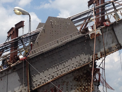
New columns will be connected to the existing non-suspended portion of the arch with gusset plates
In 2013 a joint venture of Skanska-Koch and Kiewit Construction was awarded the contract to carry out the work, with a winning bid of approximately US$743 million. Evaluation of the 41 options revealed that the least expensive were those that reused the existing arch abutments coupled with raising the roadway within the arch. A further benefit of reusing the arch is that the improvements will stay within the footprint of the existing facility so no expanded right-of-way is necessary. In addition to raising the roadway level by 19m at the crown to provide a 65.5m vertical clearance, suitable for the next generation of ships, the highway width will be increased. The original 12m-wide, four-lane highway had no emergency lanes or median barrier and was designed for up to 11,000 vehicles per day, roughly half of the current traffic volume. Once constructed the new improved roadway will include four 3.7m-wide lanes, shoulders, and a median barrier to separate vehicles travelling in opposite directions. Additionally, a new 3.7m-wide shared use path for pedestrians and cyclists will be installed outside the arch on the east side of the bridge, replacing the original 1.8m-wide walkway which is currently located on the western side.
The scheme was split into three main structural packages; the new elevated roadway deck for the main bridge span which included modification and strengthening of the existing steel arch and steel truss towers; a new segmental superstructure for the approach viaduct, to connect with the raised main bridge span, and new substructures for the approach viaducts, to be built around the existing substructures. In addition to the overall design management of the project and other ancillary items such as traffic modelling and cost estimating, HDR provided services for the first two of the three primary design packages, and the third was carried out by Parsons Brinckerhoff.
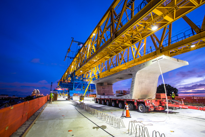
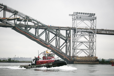
Gantry operations at night during bridge closure from 8:30PM to 5:30AM
One of the major challenges of the first structural package was the need to relocate the roadway openings at a higher level in the existing arch. Such alterations were complicated by the presence of lateral K-type bracing, spanning between the truss chords, which is continuous over the arch except where portals provide support at the existing roadway arch intersections. At these locations one bay of K-bracing has been omitted. Due to the flatter profile of the arch chords nearer the crown, each new opening will require removal of two bays of K-bracing and modification of a further bay. Work will be undertaken using a multi-step sequence using temporary bracing to allow new portal structures to be installed where bracing has been removed. Although these alterations will increase the unbraced length of the chords, thereby reducing their axial capacity, calculations have shown that the strength reduction is small and can be corrected by the addition of cover plates.
A novel solution to replace the arch roadway is being carried out by Skanska-Koch, using the sequence developed by HDR for the bid documents. The sequence begins with installation of two transfer girders parallel to the bridge span at the existing roadway level. Hydraulic jacks alleviate the load on a pair of suspender ropes and transfer the load to the girder. The existing suspender can then be removed. In the next step, transverse deck floor beams are constructed at the higher roadway level, suspended from the lower arch chords using new hangers. Temporary suspender ropes are then used to support the existing floor beams from the new floor beams above, allowing the transfer girders to be relieved of force and relocated to the next bay. To complete the deck, longitudinal steel stringers are installed between the new floor beams, prior to casting of a lightweight concrete slab. Once the roadway is raised, the proportion suspended from the lower arch chords will decrease, requiring a total of 22 fewer hangers. Accordingly, the length and height of structure supported above the upper chords at the ends of the arch will increase, which requires construction of new steel tower structures made from column and bracing members. Connections between the new and existing structures here will be achieved using gusset plate extensions bolted to the upper chords.
Despite the new wider roadway and modern traffic loading, the need for general arch strengthening was modest, which can be attributed to the significant reserve provided in the original design. Had Amman’s existing roadway been widened as he had anticipated, the total loading per arch truss would have been in the order of 2,407kg/m. Once construction works are complete the loading on the west and east trusses will be roughly 2,255kg/m, and 2,628kg/m respectively, the latter being larger due to the eccentric shared use path which has the loading impact of an additional lane of vehicles. During analysis the arch was also evaluated for increased wind loads and future light rail transit. The rating analyses for the various load combinations resulted in the need for strengthening plate additions to approximately 30% of the arch chord members, and 20% of the wind bracing members. As part of the work, all gusset plate connections were evaluated and in a limited number of cases, strengthening retrofits provided.
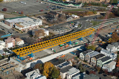
Proximity to houses is closely monitored on a daily basis for noise, dust and vibration
The design of the new approach superstructures included four separate segmental concrete box girder bridges with a total length of more than 3.2km. In order to construct this length of viaduct above the existing crossing, without closing it to traffic, some serious engineering was necessary. To eliminate the need for falsework, the approach bridges were designed to be built by segmental cantilever construction using a 152m-long, self-launching overhead gantry truss. At each new support position, box girder segments are installed in pairs, one each side of the pier, using balanced cantilever construction. Temporary post-tensioning is applied until the two cantilevers meet, at which point they can be connected using continuity tendons. The spans for the two side-by-side structures vary from 38m near the south abutment, to 83m near the south arch tower. Match-cast in Cape Charles in Virginia, and brought by barge nearly 650km on the Atlantic Ocean to the site, the box girders for the shorter spans near the abutments have a constant depth of 3m.
For spans which exceed 67m, a haunched design has been adopted for efficiency; this has a segment depth of 4.3m over the piers which transitions to a depth of 3m over the first six segments in the span. Box girder segment widths also vary, as the approach bridges each include a 7.3m-wide roadway that increases to 11m near the abutments to accommodate acceleration and deceleration lanes. The southbound structure is designed to accommodate the capacity for a future light rail on the west overhang, whilst the northbound structure includes the 3.7m-wide shared-use path on the east overhang. The two structures also carry a fire standpipe, drainage and 38 other miscellaneous utilities, placed inside the boxes for aesthetic reasons. The maximum segment weight on the project is 102t. Special multi-axle haulers are used to traverse the existing structure. All segment transport scenarios have been checked for stress in the existing approach and arch structures.
The proximity of local residents to the work site has further complicated the construction methodology. With some homes just 6m away from the bridge, noise and vibration has to be carefully monitored and controlled to minimise disruption. To increase speed of construction, precast elements were also adopted for the new reinforced concrete piers which are being installed between the existing supports. Once complete, the new approach structures from Bayonne and Staten Island will contain 13 and 11 piers respectively. To allow these ramps to connect with the raised roadway at the arch, the gradient of both approaches has increased from 4% to 5%, requiring significantly taller piers which reach a maximum height of 41m. The tallest piers, located adjacent to the steel towers at the ends of the arch, are formed from two columns of precast segments which are connected by arch braces at mid height and beneath the deck. The precast units in the upper arch brace will be transversely post-tensioned prior to the installation of the bridge deck. Shorter intermediate piers contain only one arch brace, whilst at the lower ends of the approach ramps the piers actually consist of two separate columns.
Arguably the greatest challenge of the scheme is keeping the bridge open to traffic during construction. Raising the deck of an 80-year-old arch without closing the roadway has not been done before. This unique project is made all the more impressive by the size and elegance of the steel arch, still the fourth largest in the world. HDR and SKK developed a construction sequence which ensured a northbound and southbound lane would remain open to traffic during the programme. Initially two traffic lanes will be relocated to the western, southbound side of the bridge, where they will be separated from the remaining roadway using temporary barrier walls. Kiewit, which is constructing the approaches, can then demolish the eastern side of the roadway and install precast piers and deck segments to form the northbound viaduct structures. Once the new northbound viaducts and elevated arch roadway have been completed, traffic will be moved off the existing bridge onto the new northbound structure. The existing southbound structure will then be replaced using the same procedure.
As Bd&e went to press, the construction work is approximately 40% complete. Progress has been somewhat hampered by two hard winters – hard in terms of temperature and snowfall accumulation. Precast operations are virtually complete for the northbound roadway and shortly, forms will be converted to cast the smaller box girder segments of the southbound roadway. As of early July, almost half of the units for the viaducts had been cast, mostly for the northbound approach structure, and around 10% had been erected on this part of the works. Casting of units for the southbound viaducts had only just begun. Balanced cantilever erection using overhead, self-launching gantries began in March of this year on the New Jersey side of the project. Two gantries are now operational – one on the NJ side and the other on the NY side. The gantries are identical and each weighs 445t.
Construction of the overall project began in May 2013 and the removal of the existing arch deck is scheduled to take place towards the end of next year. By that time, traffic will have been shifted to two lanes on the new upper roadway and the impediment to larger ships will have been removed. The entire project is scheduled for completion in 2018 with the completion of the western half of the roadway. PANYNJ has authorised US$1.3 billion for the entire programme of works.