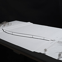

A graphical workflow concept streamlines the finite element analysis-based bridge design process of Sofistik software.
The modular concept of Sofistik's finite element software enables users to carry out demanding and complex analyses such as construction stage calculation, force optimisation, hybrid beam-shell element models and integrated analysis of 3D soil-structure interaction. But input is mainly controlled by a parametric input language, making it daunting for inexperienced users. Sofistik's new Computer Aided Bridge Design concept combines the power of a parametric background with an end-to-end graphical workflow inside the structural desktop SSD, and is intended to bring improvements to the upcoming 2010 version.
To achieve this, a software product consisting of several dedicated tasks has been developed, which supports the design process from the conceptual draft all the way to the design of all structural members. The different tasks control the high-end solver and design capabilities of the software package.
The axis-based geometry concept allows a comprehensive definition of the structural model for any bridge. Complicated route layouts can be based on a reference axis, described in the plan view by straight, circular or spiral segments and in elevation as straight or quadratic parabola elements. The assignment of one or more secondary axes relative to the reference axis enables grillages, multi-web beams and even hybrid systems to be modelled.
The members of the superstructure are then modelled and discretised with structural elements, which inherit their geometry from the underlying axis definition. Complex geometries can be modelled by placing different cross-sections, variables and dependencies - for support conditions or construction stages for example - along these axes. If the geometry is changed, the structural system will be updated automatically as references are managed automatically.
It is also possible to define any special parameter along the axis, for example for the generation of cross sections with varying depth, non effective parts and the development of a secondary axis. For the values of these variables it is possible to assign formulas. Depending on the type and number of data points, linear, quadratic or cubic functions will be evaluated.
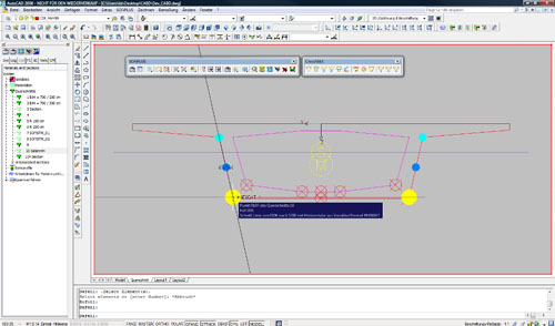
Another innovation is the graphical input facility, which allows easier and more efficient definition of unconventional cross-sectional shapes within the Autocad-based tool Crossmax. This has been fully integrated in the Sofiplus standard pre-processor. The program takes advantage of the modelling capabilities of Autocad, enabling the engineer to generate any type of cross-section. Additional components allow the selection of standard cross-section types using a template library. This part of the product is contributed by Sofistik's development and technology partner ABES.
Where variable sections exist, section properties are automatically interpolated and calculated by defining a master cross-section and assigning the variability within Crossmax. The formulae will be saved with the section and may be re-evaluated for any section with different values along an axis. In this way, longitudinal and transverse variable sections can be specified easily.
As part of the new concept, a graphical interactive task is available for the placement and design of pre- and post-tensioning. Tendons may be placed irrespective of nodes or other constraints and the program enables a full 3D geometry definition in plan, elevation and cross-sectional views. Again, the tendon layout and loss calculation will be automatically updated if the geometry is changed. The analysis offers standard features such as prestressing effects for pre-/post-tensioning and internal or external tendons; cubic 3D spline tendon geometry; calculation of losses for tendons with 3D profile and curvature; jacking and construction sequences; prestress for beam and shell structures; immediate bond with additional strain in ULS; unbonded tendons; a library of prestressing systems; tendon stress diagram and a jacking protocol.
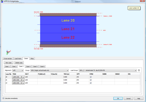
There is also a traffic loading tool, which offers simple data entry, automatic subdivision of the deck into traffic-lanes according to different design codes, establishment of influence lines and surfaces and the evaluation of load trains according to different design codes. Standard load models for road and railway can be selected from an extensive library; user defined load trains are also possible.
Following the general concept, the moving load process is based on the bridge axis as well. On bridges, the most unfavourable position of the loading is different for every single element and reaction, and is not known in advance. The evaluation of influence lines or surfaces becomes necessary for an accurate analysis of larger bridge systems with complex multi-lane traffic loading schemes. Further enhancements to this task will offer an explicit load stepping method for all kinds of systems as well. The calculation of all other load cases such as self-weight, settlement, wind and temperature effects can be carried out with graphical input using Sofistik finite element solvers.
At the end of the process, the time dependent effects of creep, shrinkage and relaxation can be investigated with the construction stage manager, which also allows the simulation of all kinds of construction methods. The construction process is managed graphically in a table using an abstract timeline with automatic recognition of prestressing stages. Powerful result enveloping and interactive graphical representation of the different reactions lead to the final step, the structural design. The design procedure includes ULS design for beam- and shell-elements and various SLS stress checks of all materials in different stages. A range of international design codes can be chosen by the user. Interactive graphical and numerical post-processing supports the report generation and allows for individual plots and data transfer to other tools and spread sheets.