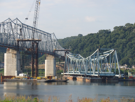
A temperature of 40°C and blazing Midwest heatwave was not enough to deter residents of the small towns of Milton, Kentucky and Madison, Indiana, from lining the banks of the Ohio River recently to watch a new steel truss span being raised slowly off barges on to temporary piers.
(Photo courtesy Deborah Crawford)
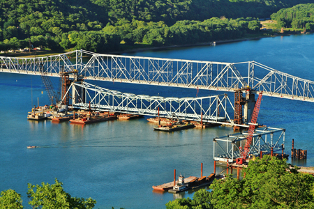
Three days earlier, the 1,520t span, which was assembled on barges alongside the Kentucky shore, had been floated into position and connected to bundles of high-tensile strand hanging from eight large strand jacks. When the lift was finished, the span had been raised 26m above the river and placed on massive steel box girders. These are temporary pier caps that will later become sliding girders for the final operation, during which the entire bridge will be moved from its temporary construction alignment to its permanent position.
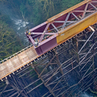
This first lift of one of the two main river spans of the new four-span continuous truss bridge, was the culmination of months of preparation; truss assembly, permanent pier rehabilitation, and temporary pier construction. In turn, it will be followed by a second lift of an even larger span, and then the two remaining spans will be cantilevered towards the abutments from the erected river spans.
Once the steel structure is complete, the concrete bridge deck, footway, and barriers will be added and the new bridge roadway temporarily tied into new approaches now being constructed. Then the traffic, which has been using the existing bridge through construction, will be diverted onto the new bridge to allow the old superstructure to be demolished.
(Photo courtesy Deborah Crawford)
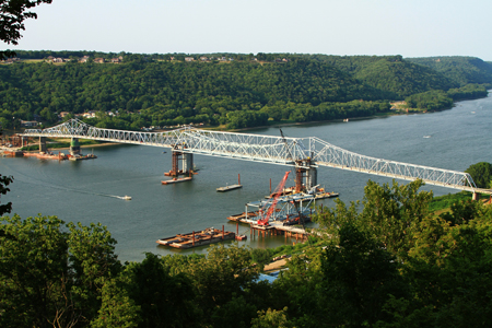
Finally, after completion of the new pier caps on the rehabilitated pier stems, the entire 740m long new superstructure will be slid 17m sideways into position on the new pier caps, during a short traffic closure. This unusual and innovative construction scheme came as a result of the bidding process; the bridge replacement was tendered in June 2010 as a design-build project with particular limitations.
The bridge owners, jointly the Kentucky Transportation Cabinet and the Indiana Department of Transportation, had studied the bridge replacement extensively with engineers and had ultimately developed the concept of rehabilitating most of the existing piers and replacing the superstructure. Superstructure replacement became the preferred option at the environmental impact assessment stage, primarily because it required no new right-of-way acquisition, minimising the impact on the two towns it connects.
In particular, Madison in Indiana is a very historic and picturesque little town, with a large historic landmark district in the town centre. Financing issues also supported the superstructure replacement option; the project was awarded a US Federal Government Transportation Investment Generating Economic Recovery or Tiger grant of US$20 million. To be eligible for these grants, projects had to be able to be completed by a certain date.
When the owner’s engineers established that the existing pier foundations were suitable for a larger bridge with rehabilitation of the pier stems and caps, this and the design-build delivery method combined made the shorter schedule more viable, enabling the project to qualify for the Tiger grant as well as making the solution more economical.
The design-build tender call was issued with some specific restrictions, including that the new bridge be a four-span continuous truss of similar appearance to the original bridge, and that it be a superstructure replacement, using four out of five existing piers, which were to be rehabilitated. The existing 1929 steel truss bridge which is very narrow and has no emergency lanes or footways, was functionally obsolete, and was deteriorating. However it is the only bridge over the Ohio River over a 116km length and consequently is a vital link to the communities on both sides of the river.
To limit the time the bridge would be out of service, tender requirements included a time component which was used in establishing the effective bid price. The design-build contractor was given the option to close it for a maximum of 365 days, but for each day the contractor proposed to close the bridge, an extra US$25,000 was added to the bid price, as an incentive for fast construction. In addition the contractor was obliged to run a ferry service while the bridge was closed.
While other bidders allowed for the maximum bridge closure of 365 days, the team of Walsh Construction, Burgess & Niple and Buckland & Taylor came up with the sliding scheme which allowed them to bid a total closure of just ten days, a difference which won the job when figured into the bid formula.
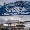
Within the US$103.7 million contract, Burgess & Niple is responsible for designing the concrete approach spans and the rehabilitation of the piers, with Buckland & Taylor carrying out both the design and the construction engineering for the steel main spans. As part of the erection of the four spans of steel trusses, totalling 740m in length, it was decided to build the two main river spans on barges and float them into position, them lift them into their temporary position using eight 330t strand jacks, two at each corner of the span, supplied and operated by VSL.
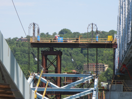
The strand jacks are supported on pairs of lifting beams raised above the truss on supports over the temporary pier and permanent pier. The two full-span lifts include some particularly challenging aspects. The nature of the truss configuration precludes shortening the lifted portion of the span, as is often done for other bridge types, to allow it to be raised to the inside of the piers. Instead the lifts at Milton Madison are made without the end floorbeams and bracing installed, allowing the truss bottom chords to extend past the pier panel point and ‘bracket’ the temporary pier tower during lifting.
Temporary bracing, set so as to clear the supports, is installed to take the place of the missing bracing and provides stability. Another challenge is maintaining a connection between the permanent concrete pier and the temporary pier tower while the truss is lifted between them. These connections, for stability and geometry control, consist of steel frames which are provided at two levels to accommodate the truss. At the start of the lift, the upper level frame was in place and the lower frame was swung down out of the way. The truss span was raised up close to the underside of the upper frame and locked off, then the lower frame was swung up beneath the truss and pinned to the pier. With this connection established, a section of the upper frame was removed and the truss lifted through.
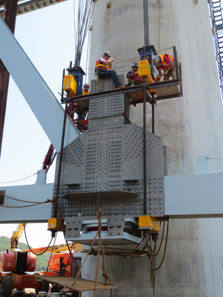
The lift was halted with the underside of the huge truss bearing hanging 300mm above the top of the temporary pier caps/sliding girders, which had yet to be inserted. The next challenge was the installation of the sliding girder, which could not be placed in advance because the truss had first to be