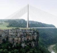
Building a second connection across the Panama Canal is in itself a challenging and difficult task, but to have to build it in record time and open it exactly 90 years after the first ship, the US cargo ship 'Ancon', celebrated the first journey through the canal, carries plenty of additional symbolic importance. The magic day will be 15 August 2004, which is also a year from the date this young nation celebrated 100 years of independence.
The second crossing is located 15km north of the existing Puente de las Americas, close to the Pedro Miguel locks and Paraiso community. Together with the new freeway sections connecting Arraiján in the west with Cerro Patacón in the east, the new connection is expected to remove 50% of the traffic from the existing 40 year old structure. Its location at the Culebra Cutting was chosen because the hills on each side of the canal allow for a relatively short bridge of 1052m; all the same, it will have a huge 80m vertical clearance above the canal. The Culebra Cutting was made famous during construction of the canal because it was the scene of regular landslides which constantly delayed its completion.
A floating crane named Titan is permanently stationed in the canal and is used for rescue services and repair of lock gates; this vessel must be able to pass below the new bridge and was the main reason for this unusually high vertical clearance. Titan is one of three huge cranes which were originally built in Germany and was taken by the USA as reparation after the World War II. It has been stationed since then in the US-owned canal. In addition, a possible future widening of the canal from 192m to 275m had to be considered in the horizontal clearance of the bridge.
In October 2000 the Panamanian Ministry of Public Works invited consultants to submit concepts for a design competition. A proposal by TY Lin International for a cable-stayed concrete bridge was successful and the consultant was selected to carry out the design of the bridge in three steps - concept, preliminary and detailed design. The structure consists of seven spans; four side spans ranging between 46m and 66m, a main span of 420m and two back-spans of 200m. The alignment is largely straight in plan, except for two spans on the west side. In elevation the highest point is found above the canal with slopes of 3% to each side. Foundations vary from raft foundations directly on rock or soil and deep foundations of up to 35m-long piles. Each pier foundation had very specific conditions, different from the neighbouring one, and final modifications had to be made after excavation.
The cross-section of the superstructure consists of a 34m wide box of 4.5m constant depth with wide cantilevers supported by cross-girders every 6m. This box is suspended in one central cable plane every 6m from steel delta frames. Three traffic lanes plus shoulders on each side are separated by a central walkway which passes through openings in the king post towers in the bridge axis. The superstructure is post-tensioned in both directions. Piers and the tower cross-section on top of the deck are of similar shape but turned by 90o. The long sides of what are basically rectangular sections have a convex shape that is either curved or polygonal. On the short side the straight wall is set back 250mm, marking the walls at both corners.
The tower section below the deck starts at the foundation on a 9.4m square base and tapers to 6m by 4.5m at the top.
All piers are of constant section over their height. The towers are tapered in both directions on a slope of 1:108.
The design is based on AASHTO standard specifications for highway bridges and AASHTO guide specifications for segmental concrete bridges. Seismic activity is frequently observed in Panama and the structure was designed for peak ground acceleration of 0.21g (functionality evaluation earthquake) and 0.33g (safety evaluation earthquake).
Time constraints on the programme meant that only a limited number of elements of the design concept could only be optimised during detailed design. The bearing conditions of the superstructure were modified to a solution with that had less restraint, hence reducing the seismic reactions on piers and foundations. The superstructure and the cable suspension was detailed as per the given concept of the preliminary design, and at the last moment, the proposed 40mm concrete overlay was replaced by integral concrete overlay to speed completion and eliminate the possibility of problems in achieving a good quality result with such a thin overlay.
Contractor Bilfinger Berger was awarded a contract in March 2002 to build the bridge in just 29 months, including clearance of dense forest and major landscaping work. A total of 710,000m2 of earth had to be moved and new slopes had to be secured before construction of the bridge could begin.
Construction of the superstructure was planned to be carried out using typical free cantilevering segmental erection of the stayed portion of the bridge. The approach spans of both sides would be built by using cast-in-place segments span by span. Obviously the main bridge was on the critical path right from the start. Optimisation of construction of the segments of the superstructure was the primary goal from the beginning. Bilfinger Berger had employed Leonhardt Andra und Partner during the tender stage to develop its construction concept, and this was further refined during detailing. The key elements, of course, were the pier table, the form traveller and modifications of the section to allow for extremely short cycles.
In order to speed up the construction, form travellers have been used as an integrated part of the pier table falsework, raised using heavy lifting equipment in just two lifts. After construction of the pier tables, the back to back connection was opened and the travellers launched into the next position.
During casting, the main trusses of the form travellers are attached by prestressing to the existing structure. For the launching procedure, one transverse, C-framed girder carries the weight of the traveller and slides on top of the girder over the webs of the box. At the rear end of the traveller are platforms to allow for finishing work under the deck, if required.
Precast elements are used within the segment where post-tensioning or cable forces need to be applied after less than 12 hours. The complete form traveller was planned to be lowered by approximately 1.1m to clear the cross-beam, launched forward 6m and raised within hours in order to allow for the placement of preassembled rebar cages including precast elements and the steel diaphragms with the cable anchorage on the same day.
After the closure pour in the centre of the main span, the traveller must be returned to the towers and lowered in front of them. Ship traffic on the canal must not be interrupted at all during construction, not even for lowering of the form travellers. The Canal Authority even forbids staff to cross the canal in a small boat, meaning a detour of 20km over the Puente de la Americas to reach the east tower from the site office.
Approach spans are built on scaffolding with one intermediate support. After the first step, in which the U-section of the box is poured over the full span length, the deck is then poured in segments of 12m length. After completion of one span the scaffolding is removed and assembled again in the following span.
Right from the beginning the Puente Centenario was planned as a fast track project, where detailed design and construction were expected to be carried out alm