A new foot and cycle bridge linking two historically separate communities is due to be completed this month (May). The suspension structure, which is designed to represent two linked arms, connects the two banks of the River Foyle in one of the main cities in Northern Ireland.
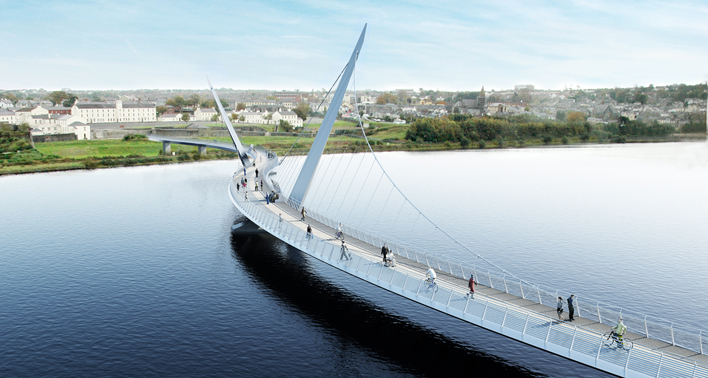
The Peace Bridge is intended to reunite two communities in the city of Derry-Londonderry which have in the past been divided by the political situation in Northern Ireland, as well as by the river. The extent of the division between the two sides is underlined by the fact that even the city’s name is disputed.
With the opening of the bridge, the heart of the city centre will be linked to the former army barracks at Ebrington, which is currently being redeveloped. The bridge project is being funded through the EU Peace III Shared Space programme.
With this turbulent historical context, coming up with a suitable design was a more demanding process than ever. The site itself posed physical constraints on the design team, with the need to connect strong horizontal axes on each side of the river. These axes did not coincide naturally, and it was up to the alignment of the bridge to unite them.
From a more symbolic point of view, it was vital that the structural form of the bridge did not favour one side of the river over the other, and hence a symmetrical solution was necessary. In celebrating the connection and reunion of the two banks, the design should serve both but belong to neither. Additionally a navigation channel width of 60m had to be retained in the river.
The concept for the crossing, which was created by architect Wilkinson Eyre and structural engineer Aecom, is intended to mimic the interlocking of two arms in a gesture of support and friendship. In structural engineering terms, the bridge is effectively formed of two single-tower self-anchored suspension structures which overlap on the main span. In plan the deck is s-shaped and each of the two towers is inclined away from the deck. The design exploits the reverse curvature of the deck and the inclined towers and suspension cables to provide balancing radial forces by which it achieves its stability. The parapets are twin stainless steel plate posts at 2.2m centres with 11 stainless steel, tensioned wire ropes, and tubular handrail and top rail.
Tenders for the project were invited in late 2008 and the US$14 million design and build contract was awarded to main contractor Graham Construction. Work began on site in November 2009 and is due to be completed in May 2011.
Each half of the s-shape is supported by hangers from main suspension cables, with two land spans on the eastern end. The main suspension bridge is some 250m long and crosses the river with a main span of 96m. The land spans are approximately 60m long and carry the bridge over a railway line to connect to the elevated ground at the east bank – the bridge rises 7.5m along its length.
A continuous steel box girder with diaphragms and cantilever beams at 4.4m centres forms the main bridge deck, and the ends of the cantilever beams are linked by a continuous C-girder. The total width of the deck varies between 4.6m and 5.6m.
Four main cables, each with 14 hangers, support the deck; the top ends of the main cables are anchored at the two inclined towers, which are each nearly 40m long, and the lower ends connect into trumpet anchorages on the sides of the box girder.
The main cables are formed of 115mm-diameter locked-coil cables, while most of the hangers are 35mm-diameter spiral wound cables connected to the main cables by cast steel hanger clamps. The shorter hangers are connected by special turnbuckles or a direct weld between the hanger clamp and deck. S355 weathering steel is used for the towers and box girders; the cantilever beams and C-girder are made from S355 steel. The total mass of the superstructure is approximately 1,000t.
Steelwork contractor Rowecord Engineering was brought on board at tender stage to assist with development of a cost-effective design for the steel elements of the structure, and the design-build collaboration between Graham Construction and the design team enabled adaptations to the substructure which allowed the contractor to use equipment it already had available.
In all, the bridge is supported at seven points along its length – four supports in the river for the main bridge, an intermediate land support and two abutments. Given the poor soil conditions, piled foundations were required for all river piers and these are formed of groups of 1m-diameter steel tubular piles approximately 20m long, connected to concrete pilecaps via shear connectors. Foundations had to be built in the deep, fast-flowing river. Tubular steel piles were driven with precast elements set on top to allow the pilecap to be constructed ‘in the dry’.
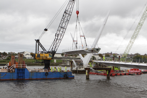
The piles were driven with an hydraulic drop hammer using a 100t crawler crane on a floating barge with the piles transported from Londonderry Port, some 7km downstream. Due to the nature of the structure, it was important that the piles were positioned to a high level of accuracy, something not easily achieved in the fast flowing River Foyle. Large holding-down bolt frames were cast into the pilecaps at the tower positions.
Because of the self-anchored structural form, the fabricated bridge deck had to be lifted into place in sections before the cables and hangers were installed. Additional temporary supports were required in the river to reduce the span to approximately 30m, so pairs of tubular steel piles were driven to a similar level as the permanent piles, and a steel frame was installed on top to take the weight of the deck sections and allow access for welding the joints. Temporary supports were also required at the permanent support positions to allow accurate positioning and accommodate movement during cable stressing.
Fabrication and erection of the bridge deck and towers and installation of the cables and hangers was subcontracted to Rowecord Engineering.
Before fabrication, a complete 3D computer model of the bridge towers and deck was created; this enabled the very complex structure to be readily visualised, and it simplified the checking process. The model was then used to produce component, fabrication and assembly drawings.
For construction purposes, the bridge was split into twelve sections along its length with each box section having a substantial construction diaphragm at each end. Consecutive boxes were trial-assembled in their final order in the fabrication shop and the end diaphragms were adjusted before welding so that the correct plan and elevation of the bridge was maintained throughout its length. Each box section was joined to the next by bolting through the end diaphragms, then butt welding the box plates. The diaphragms and bolts were designed to ensure continuity of the longitudinal stiffeners as well as to aid erection.
As it was not practical to trial-assemble the whole bridge, each box was surveyed in the fabrication shop and the complete length of the bridge was modelled from those survey results.
The towers are nearly 40m long and weigh approximately 60t each. Each is connected to the steel plate cast into the pile cap by 26, high-tensile steel tendons which were stressed after erection of the towers.
Although Rowecord’s fabrication works in Newport, South Wales has direct access