Coordination between four federal transportation authorities was one of the simpler considerations that had to be addressed by engineers in advance of the major lifting operation that took place on the Huey P Long Bridge over the Mississippi River this summer.
Phase three of a seven-year project in which the existing bridge will be widened to accommodate extra capacity for road traffic includes a series of complex procedures in which twin trusses are simultaneously raised into place on each side of the existing structure.
The Huey P Long Bridge in Louisiana, USA, is a four-span steel truss bridge that carries a two-track railroad line over the Mississippi River with two lanes of US90 on each side of the tracks. The bridge was opened in 1935 and is owned by the New Orleans Public Belt Railroad. To enhance economic development in Louisiana, the Transportation Infrastructure Model for Economic Development Program initiated a project to widen the existing bridge to carry three lanes of traffic with an emergency lane in each direction in addition to the existing two rail lines.
The US$1.2 billion widening project started in 2006 and is expected to be completed in 2013. Phase three of the four-phase construction process, which includes the main bridge truss widening, was awarded to the MTI joint venture of Massman Construction Company, Traylor Bros and IHI. The widening of the four spans is being carried out one span at a time, and MTI hired consultant HNTB to devise the span-by-span erection method. Last November, widening of the west bank span began using the ‘stick-build’ method, in which each member of the span is individually placed.
In order to minimise the use of falsework and river closures in the main navigation and auxiliary channels, the widening of the three other spans will be carried out by assembling trusses on barges near the shore, then floating them out to the bridge, and lifting them into place using strand jacks. This method requires both the upstream and downstream trusses of each bridge span to be lifted and set simultaneously in order to avoid any unbalanced forces being imposed on the bridge.
Applied Geomechanics was contracted to design and install a remote monitoring system to measure real-time truss deformations during the first ten hour operation in which a 161m-long, 2,650t steel truss span assembly was raised 40m into position.
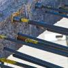
The prefabricated pair of trusses spanning piers I and II were assembled on barges with stability frames and floor beams near shore. MTI built a four-barge system connected by three sectional barges. HNTB designed the stability frame/floor beam assembly which was built on the barge platform to help support the trusses and keep them plumb throughout erection. The stability frame was also used to help support the twin trusses during transport to the bridge, during the lifting operation and provided a means to skid the trusses laterally for the final setting on the piers.
Construction of these twin trusses began in April and was completed by the end of May. The lift was carried out the weekend of 19/20 June, a complex operation that needed coordination between all four transportation departments – the Federal Aviation Administration for crane heights; the railroad for the track closure, the DOT for the bridge traffic closure and the coastguard for temporary closure of the main navigation channel. On Friday 18 June the trusses were barged into place under the bridge and connected to lifting tendons from the 900t strand jacks. The lifting operation was performed by Mammoet; although Mammoet monitored hydraulic pressures, overall lifting and setting displacements during the lifting and skidding operation, the truss needed to be monitored to ensure there was no overstressing or buckling of any elements.
The three critical phases for monitoring were; the launching and transport of the trusses on the barges to the bridge; the lifting operation itself; and the skidding operation during which the trusses were pulled 4.5m laterally in towards the bridge and set in place.
The biggest concern for MTI and HNTB was the danger of out-of-plane distortion, primarily ‘sweeping’ of the truss. Since the 161m-long truss would be lifted at the end points, any tilting of the truss could initiate buckling. Therefore, the two most important parameters to measure were tilt and out-of-plane deflection of the truss. AGI worked with MTI and HNTB to develop an instrumentation layout that used tilt meters and laser distance sensors.
The tilt meters were installed on the vertical stability frame members and measured tilt in both the longitudinal and transverse directions of the truss. Since the truss was fixed to the stability frame during transport and lifting, measurement of the vertical member of the stability frame was representative of the truss tilt. A total of eight biaxial tilt meters were used - four on each truss/frame.
Laser distance sensors were used to measure truss out-of plane distortion. The concept of using distance sensors to measure deflection was developed by AGI for this project. The principle is that the distance does not change between the fixed laser and the fixed target. The target is mounted at 45º from the deflection measurement of interest, and as the truss deflects, the laser reflects at a different location on the target – either closer or further away - and records a difference in distance. Since the target is placed at 45º the distance change is equal to the deflection change. This concept was verified by AGI prior to implementation. A total of ten lasers were used to measure out-of-plane truss distortion – five on each truss. The total bottom chord end deflections were measured and three top chord deflections were measured on each truss.
All sensors were hardwired to a data logger placed on the stability frame/truss. The data logger contained a radio modem to transmit collected data to a laptop computer with multiple display panels. Since the truss and data logger system were remotely positioned on the barge during transport, lifting and setting, up to 16 hours of battery backup was provided for uninterrupted data collection and transmission.
The monitoring station was set up under the bridge deck on top of Pier II. Data was continuously transmitted and updated approximately every five seconds. Data was under constant review by HNTB engineers and decisions made for controlling the lift were based on real-time truss tilt/deflection measurements.
To aid in the review of data, AGI worked with MTI and HNTB to develop a graphical representation of truss tilt and deformation. For each truss and ‘birds eye’ view of the truss was displayed on separate screens to show ‘sweeping’ of the truss during the lifting and skidding operation.
Throughout the 18-hour lifting and setting operation, radio transmission of data to the remote monitoring station was never lost. It supplied constant information that was used for the decision-making process throughout the operation.
HNTB vice president and bridge group director John Brestin acknowledges the importance of this system. “The monitoring system was vital to the lift operation. We were able to use it in real time and know exactly what was happening with the lift,” he says. “It allowed us to make adjustments to the attitude of the truss ‘on the fly’ without slowing down the operation – something that could not have been achieved with traditional survey methods.
“Once we confirmed that the monitoring system was giving us results that agreed with survey and visual inspection if gav