The growing acceptance of building information modelling, or BIM, is an acknowledgement that the building industry has fundamentally changed. Project documentation is no longer simply a set of paper-based two-dimensional orthographic projection drawings, it is live views from a three-dimensional virtual model. The building information model is a three-dimensional geometric model that is data-rich and the information contained within it can be used for many other purposes such as predicting energy consumption, structural performance, cost, scheduling, and identifying clashes between systems ahead of construction. It can even be leveraged for facility management uses.
However, this is more than a set of software programs; it is a process which is inclusive and may involve a wide group of stakeholders from design and construction, to operation and maintenance. It is an integrated database of construction information, including building components.
So a BIM solid model is an integrated, digital database, informed by the architectural, engineering, construction and operation industries, that consists of 3D parametric objects and allows interoperability. It is also possible to add parameters to the 3D model; in this way the model can be said to be programmable.
The model organisation can be classified into dimensions which range from 2D to 7D. Clearly 2D refers to flat drawings such as plans, sections and elevations, while 3D means the 3D digital model. Going into 4D includes the integration of time in the form of 3D phasing and construction sequences; 5D adds the aspect of cost, 6D deals with lifecycle, facility and energy management and finally 7D introduces safety issues.
Architects, engineers and consultants are heavily involved in the design/build process, and BIM has a major role in each of these phases: planning, schematic design, design development, construction documentation, bidding, construction phase and lifecycle.
Each phase of design can be managed by building information modelling, from planning through schematic design to construction documents and project completion. For analytical modelling, the use of BIM has several advantages; for example the major effort on the project can be aimed towards schematic design because of the time needed to create the parametric 3D model. Changes made during this phase can be cheaper to implement than if they are made subsequently, and they can have more impact on the project.
Finally the 3D model can also be used for simulation studies. One important advantage of a building information model is the coordination between the 2D and 3D information. As the project components are updated and increased in complexity, those changes will show on the update sheets. Analysis is a part of every phase of the design process, so as the level of information in themodel increases, greater accuracy in the analysis results becomes possible.
During the process of creating construction documents, professional firms find that building information modelling is incredibly powerful in comparison to other CAD documentation methods. The output from this phase is a set of integrated documents that are used in the bidding process and for the construction of the project.
Finally, the building information model is a fundamental component of the bidding and contract administration, making it easier for contractors to understand the complexities of the project for which they are bidding. Detailed cost estimation is easier and questions about the complexity of materials and construction methods can be answered more quickly.
However with such complex models being used by so many parties, the question of compatibility between software arises. The need to automatically exchange models and other data between different software platforms remains one of the biggest barriers to fully integrated and collaborative project delivery.
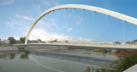
Rendering of the New Cittadella Bridge (Comune di Alessandria)
During the development of the design for the New Cittadella Bridge in Alessandria in Italy, the stakeholders involved in the final design and construction process assumed BIM procedures and software interoperability to permit the management of the complex geometry created by the conceptual design. The bridge, a 200m-long suspended arch bridge is being built for owner Città di Alessandria to a design by architect Richard Meier & Partners. Mantoan Progettazioni is BIM designer for the project.
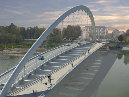
The bridge, which has a 200m-long span, is under construction at the moment (Comune di Alessandria)
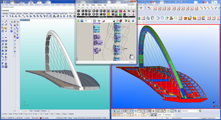
Powerful parametric and generative modelling of projects was enabled by using plug-ins for Grasshopper and Rhinoceros. Generative BIM model exchange is provided by using a combination of open BIM formats, primarily industry foundation class, and direct application programming interface interaction to software packages including Revit, Archicad, Digital Project and Tekla.
Structural analysis models can be exchanged with many widely-used analysis software packages. Three-dimensional computer-aided design processes primarily use geometric elements such as solids, surfaces or other entities; the geometric models can be used to verify and to solve geometric problems. The BIM designers have used Rhinoceros and Grasshopper to manage the complex shape of the deck and the cladding of the bridge in order to clarify geometric conditions of individual parts, or of the bridge as a whole, to visualise the result from a purely geometric point of view and for collision detection in order to implement different construction solutions. Furthermore, the building information model includes information about mass, element specification, economy and programme and by using industry foundation class the designers are able to share this model with all the stakeholders involved in the design and construction process.
Since project presentation takes a significant role in the different design process phases, this case study aims to demonstrate that, by using a building information model from the outset, a 3D model is available for the following functions: for technical information verification, including geometry, (size and shape), position and relation between the parts and the whole; also for project navigation allowing the bridge to be presented three-dimensionally in real time in order to enable a higher quality exploration of the project.
The process of using building information modelling for the New Cittadella Bridge began with a commitment to coordination between all the stakeholders in the project. It is vital to establish the goals that all parties want to obtain right at the start. Conversations with the main contractor Itinera, the steel contractor Cimolai, the architect and the structural engineer were necessary to gain a clear understanding of what they expected from the building information modelling process. The BIM designers were asked to produce a building information model that would be appropriate to use for geometry investigation and rationalisation, construction documents, software interoperability, construction and erection simulation and cost estimation.
From the outset, all the necessary information was collected that was required to set up guidelines for modelling the bridge as preliminary drawings, sketches, specifications and calculation reports. Following the analysis of these documents, all of the information was collated, to underline the potential differences between them. This information sharing formed the basis of a document that was used to define the building information modelling execution plan.
One of the most exciting aspects of the new bridge is its historical reference to an original stone and brick bridge which dates from the Napoleonic era. The architect has paid homage to this by mimicking the arch form, albeit while introducing a suspended deck. In order to counterbalance the inflection of the vehicular road bowing out towards the north, the arch that carries both spans is curved to the south. The weight of the pedestrian way on the opposite side of the arch helps to balance the dead load of the overall structure.
In order to avoid any interference with the existing structure, a 3D parametric model was set up and used to calculate the distance between the bottom of the deck and the upper part of existing bridge. The distance was analysed by an algorithm, using the 3D model and allowing the average, maximum and minimum distances between the deck cladding and the old structure of the bridge to be calculated. The algorithm was written in Grasshopper using ‘visual scripting’ which enabled the designer to maintain control of the process during the analysis through the use of data sharing and interpolation.
Having obtained an acceptable value, the axis of the primary deck structure and the guidelines of the arch were defined as a first step. The investigation of this geometry by the use of the BIM model was fundamental to the process of transmitting information to contractors, including the position of the abutments, foundations and so on. In addition, it allowed the designer to monitor the form of the bridge against the architect’s original design intent during the process of geometry rationalisation. The model was kept up to date throughout this process by adding all data related to the geometry definition.
Again, the data was managed by an algorithm that could change the configuration of the bridge parametrically to respect the aesthetic constraints as well as the building specification and calculations such as precamber, for the next phase of construction document delivery. The algorithm allowed the designer to modify the configuration of entire bridge by simply changing numeric values in the model. It was also possible to modify elements such as height, thickness, holes, member chamfers and above all it allowed the management of complex shapes such as double curvature planes.
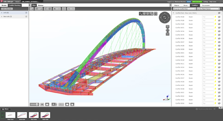
The arch form was constituted by wrap plates, which was made possible thanks to the strong interoperability of Rhinoceros/Grasshopper and Tekla structures. Then, by using API, the ‘surface model’ obtained from the integration of Rhinoceros and Grasshopper could be switched to any other software without the need for complex exporting or importing procedures. In this way the designer only needed to set up a single model from the beginning and then implement it by adding data step by step. This process was particularly beneficial because the management of shape, geometry change and detailing could be carried out simultaneously. Then the model could be issued directly to the steel fabricator by a unique process that allows a single model to be used by different software. This process is described as software interoperability – a phenomenon that allows two different software packages to interact without the loss of information. At this time, the 3D model was complete, and could be used for clash detection purposes, thereby allowing the avoidance of errors during the steel fabrication phase, mechanical & electrical work, concrete slabs and hangers and so on.
The next stage dealt with the modelling of temporary structures, which are extremely important for the erection of the bridge. Firstly, it was necessary to understand the erection procedure; once this had been considered, the supporting structure was modelled and by doing so, it was possible to identify any potential clashes during the consequential erection phases. The building information model allows modification of the configuration of the bridge in accordance with the different stages imposed on the design by the conditioning of the precamber, and analysis of the displacement of the bridge. The designer can have confidence in the position of each member in order to ensure a safe erection procedure and avoid mistakes in one of the most difficult phases of the bridge project.
The extensive use of BIM virtual mock-ups focused on exterior detailing proved to be a vital asset to the team and were an invaluable coordination tool in many areas of the bridge. By sharing the BIM model with all the stakeholders, numerous deficiencies were discovered and solved before becoming problems on the construction site. Additional costs typically associated with detail modification during fabrication or erection were avoided.
At the end of modelling process a data-rich model was obtained that could be used by all the stakeholders. The contractors used the model to extract bills of quantities, construction documents, CNC files, and coordinates; the architect was able to use it to visualise the design; and the project managers used the model for phasing and cost control. This project demonstrated a variety of opportunities related to BIM procedures.
It provided clarity to important information that could have been lost in the complexity of the design and construction process. By enabling teams and stakeholders at all levels, new degrees of certainty were established in the process by grounding decision-making, collaboration, and delivery with a data-centric approach. The complex geometry of the bridge required the implementation of a rigorous plan for both documentation and project coordination. Due to its high level of complexity, the project would not have been built without clear process planning and expert coordination of technology.
As an emerging core competency of design thinking, it has become critical to engage in a discourse that includes BIM and computational design as essential components of the building process for all the future projects in order to get 3D parametric model with associative data and the ability to operate seamlessly with other programs.
Massimo Mantoan is founder of Mantoan Progettazioni

