The Molonglo River Bridge is designed for dam-break flood loads
The new 200m-long Molonglo River Bridge is a critical piece of infrastructure that will provide a major arterial road link, utility services and a transport corridor to downtown Molonglo, Canberra’s newest suburb currently in development. When completed in the third quarter of 2026, this final link will replace a low-level causeway subject to frequent closures due to flooding.
The crossing is the largest weathering steel bridge project in Canberra, and its 80m-long single weathering steel span also makes it the longest of its kind in the southern hemisphere. BMD Constructions was engaged as the lead contractor by Infrastructure Canberra, while GHD and pitt&sherry – in association with COWI (UK) – provided tender and detailed design services.
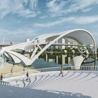
To ensure the bridge design responded to the aesthetic, environment and scale of the Molonglo Valley and its river corridor, the Government of the Australian Capital Territory (ACT) outlined architectural parameters at the outset of the project. As a highly visible piece of infrastructure, it was specified that the new high-level link visually integrate within the surrounding landscape.
With a weathering steel bridge already in the Molonglo area (Butters Bridge) and another in planning just a few kilometres away, the ACT Government recognised the aesthetic need for establishing common design features for a shared unique context. A ‘family of bridges’ concept was workshopped and developed using weathering steel in its key components.
Terex Demag CC8800-1, one of only two in Australia
To meet the architectural requirements, pitt&sherry in association with COWI prepared the detailed design for a three-span superstructure composed of weathering steel haunched box girders and pier columns encased in non-structural weathering steel. The bridge features two separate decks carrying northbound and southbound carriageways in a 60m, 80m and 60m span arrangement, ensuring the piers are outside the normal waterflow of the Molonglo River. Each accommodates two traffic lanes, shoulders and a 3.5m-wide shared-user path, with a medium performance traffic barrier separating the shared-user path and the roadway. The bridge also considers a future 10m-wide light rail crossing located in between the road bridge decks.
The superstructure is formed by twin trapezoidal steel box girders made composite with a reinforced concrete deck. Box girders are continuous with varying depth incorporating a 4m-deep haunched section over each pier and a 2m-deep section at end spans. Flange plates vary between 20mm and 80mm, and the web plates thicknesses range from 20mm to 35mm.
The bridge was designed for the typical loads outlined in Australian Bridge Design Code AS 5100.2 as well as additional specific loads. These include the loads of the future light rail bridge, which the bridge substructure has been designed to support. It is assumed that the superstructure will be a continuous steel composite trapezoidal box girder with similar elevation to that of the road bridge, and with the same articulation, with a longitudinal fixed point at Abutment A.
Also accounted for in the design are future construction loads. It was anticipated that the future light rail superstructure would be installed from the deck of the new carriageways to eliminate disturbance to the environmentally significant valley, home to the native platypus. Installation of the superstructure steelwork girder segments was assumed to be undertaken by two 500t mobile cranes (or similar) working in tandem.
Lastly, the bridge was also designed to dam-break flood loads. The Molonglo River connects to the nearby Scrivener Dam and Lake Burley Griffin, the former being an important flood control structure for the Molonglo-Queanbeyan section of the Murrumbidgee catchment. For this reason, the bridge was designed to withstand floods up to the 2,000-year ARI and a Sunny Day dam break event, without loss of structural integrity.
The ACT Government provided an equitable sharing of risk with the Develop, Design and Construction model, which eliminated initial risk and allowed the design and construction team the freedom to innovate. Their focus was on simplifying construction, improving access, increasing safety during maintenance and inspections, as well as improving the sustainability of the design solution.
While the initial concept design was buildable, it was not as sustainable as it could be. It presented a bridge superstructure formed by three narrow rectangular box girders for each deck, with an overall length of 225m and an unequal span arrangement of 60m, 93m and 72m.
These three girders did not maximise the advantage of the associated torsional stiffness, nor did they use the deck slab to provide efficient transverse capacity. The tender and detailed design was developed to maximise the efficiency of wider trapezoidal box girders and the composite concrete deck slab by adopting constant spans between the webs of the respective box girders.
Changing from three narrow rectangular boxes to two wider trapezoidal boxes led to safer construction with fewer lifting operations and more stable box girders. It also gave rise to the possibility of incorporating an abutment gallery, which facilitated safe access into the box girders, around the bearings, and to the expansion joints. Additionally, eliminating confined spaces and reducing the amount of internal bracing would increase safety during maintenance and inspection. Finally, it reduced carbon impact due to a material reduction.
The Molonglo Bridge features a steel composite superstructure with weathering steel plates 16mm to 80mm thick. The specified steel grade WR350 was assessed for brittle fracture requirements in accordance with Section 14 of AS 5100.6 to determine appropriate sub-grades in terms of impact testing options L0 and L20. It was noted that AS 5100.6 requirements are based on the principles used in the old BS 5400-3:1982, which have been significantly revised in the latest British Standards and Eurocodes to reflect current knowledge. Using AS 5100.6 results in any plates greater than 20mm thickness needing to be sub-grade L20, even though the design service temperature is only -3°C.
COWI undertook a brittle fracture study and confirmed the justification for adopting Eurocode requirements for the structure. The ACT Government supported the recommendations, with the result that the steel subgrade for all steel up to 65mm-thick was grade L0. For steel thicknesses 65mm and above, weathering steel was required to be grade L20.
The ACT Government stipulated that there be no long-term closures of Coppins Crossing Road during construction. BMD considered several construction methodologies in the early planning stages and decided on a heavy-lift crane option. The pitt&sherry temporary works design team worked closely with BMD to provide the required temporary supports and restraints and to confirm lifting assumptions.
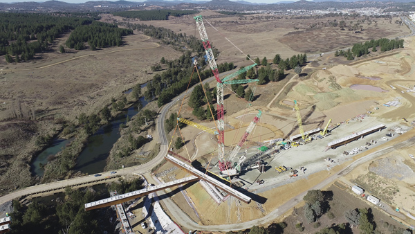
The crane chosen for the girder installation was a Terex Demag CC8800-1. This 1,600t crane is one of only two in Australia and was supplied to the project by Tutt Bryant. The Demag was located at Henderson, Fremantle, Western Australia, where it was dismantled and transported to Canberra over a period of three weeks. While it featured a main boom 66m in length, an additional 42m-long main boom and a 78m-long jib were also needed to complete the lifts.
The main crane counterweight was 355t and a super-lift arrangement with 640t of counterweight was required, as well as the use of 26 large steel bog-mats. Five oversize overmass transport vehicles and 120 semi-trailer loads relocated the crane. Its assembly required two tracked service cranes with 250t and 275t capacity, with erection and certification taking four weeks.
Despite its size, the Demag did not have the capacity to install all the girder segments from one abutment. After part of the girders had been installed from Abutment B, it had to de-rigged and re-established at Abutment A to complete installation. Two specific lifting arrangements had to be considered, each requiring different crane configurations. Due to transportation limitations, the girder segments were transported in 40m-long segments to site, where they were installed in a three-phase sequence.
Noting that girder assembly lifts were considerable and that they had to match the grade of the bridge accurately, it was decided to incorporate an Enerpac Synchoist system in the rigging arrangement. This system added 8t to the lift weight, but it provided the capability for +/-1mm adjustments in the longitudinal grade and transverse crossfall during positioning of the girder assemblies on the pier and abutment supports. This was vital to accurately and successfully splice the centre segments.
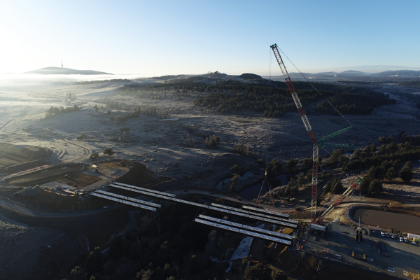
Phase 1 of construction consisted of splicing a haunched pier segment and an abutment segment and then installing the 80m segment from Abutment B. The total weight of the first four 80m-long segments – including lifting gear and hook block – was 320t.
Prior to release from the hook, the girder assemblies were seated on temporary hydraulic jacks and sledge plates, supported by temporary propping. These jacks and sledge plates provided lateral and vertical adjustment during the subsequent installation of the centre segments. The arrangement enabled the push-out or push-back of the abutment/pier girder assembly during the positioning of centre segments.
Phase 2 involved demobilising at Abutment B and re-establishing the crane at Abutment A for the next four 80m-long spliced girder segments of the southbound and northbound bridges. As in Phase 1, girder assemblies were placed on temporary jacks, but permanent bracing was used rather than temporary supports.
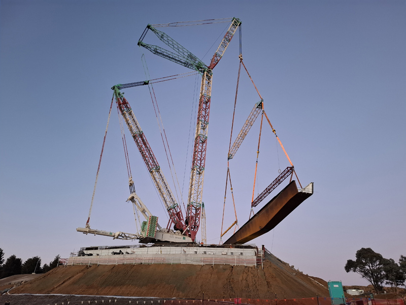
The four 40m-long centre ‘closing’ section girder segments were installed during Phase 3, also from Abutment A. This was the most critical lift, 106t at 115m, which called for a longer reach in the Demag: it was thus re-configured with a 78m luffing jib in place of the 42m section.
The girder assemblies that had been installed in Phase 1 were then pulled back towards Abutment B by around 100mm, using the hydraulic jack and sledge plate arrangement, to provide sufficient space to lower the centre segment. Using the Enerpac Synchoist system the centre segment was aligned with the girder assemblies installed in Phase 2, and splicing conducted. The Phase 1 girder assemblies were then pushed forward and adjusted vertically to meet with the partially installed centre segment. Finally, the load on the Demag was fully released and all girder bolts fully tensioned.
The massive Demag crane had to be derigged and re-established at the opposite abutment to install the 80m-long steel segments
With the installation of the box girders successfully completed at the end of June 2025, the next stage will be the installation of the precast concrete deck panels and the in-situ concrete deck.
The successful design and construction of the Molonglo River Bridge could not have been achieved without the outstanding collaboration that was fostered between the client, iCBR/MPC, the principal’s authorised representative, SMEC, BMD, pitt&sherry, COWI, GHD and other providers for the project, including Tutt Bryant.
The project will be open in 2026, with bridge construction due for completion in February 2026.
Irene Scott is executive director and senior principal engineer at pitt&sherry
Client: Infrastructure Canberra
Client’s Representative: SMEC
Contractor: BMD Constructions
Superstructure Design: COWI (UK), pitt&sherry
Substructure and Temporary Works Design: pitt&sherry
Civil Works Design: GHD
Architect: Cox Architects
Fabricator: Civmec
Proof Engineer: Stantec