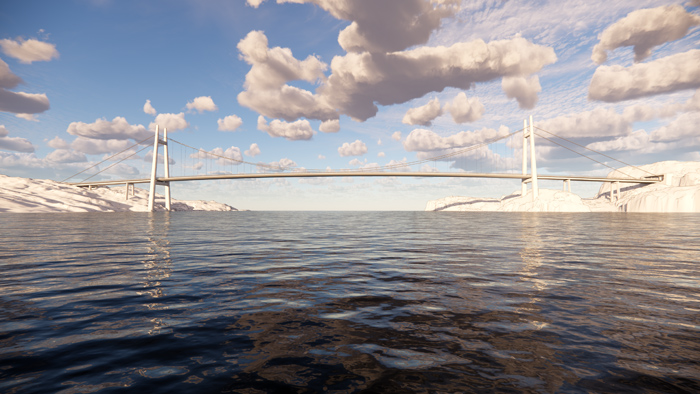
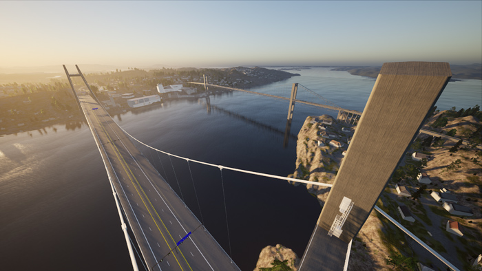
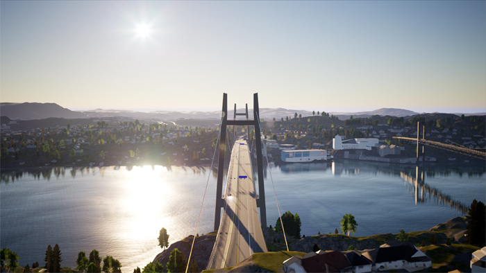
Render of the New Sotra Bridge (all images courtesy of Webuild/NPRA)
Within the preparation phase for the New Sotra Bridge are extensive access works that include multiple temporary roads, tunnels and rock blasting. The suspension bridge is part of a US$2.1-billion programme that aims to improve connectivity between the Municipality of Bergen and the island of Sotra, around 400km west of Oslo. The new link covers a total of 12.5km of primary and secondary tunnels as well as a number of smaller bridges, viaducts and underpasses.
The project was awarded by the Norwegian Public Roads Administration to Sotra Link, an alliance formed by Macquarie Capital, SK Ecoplant and Webuild, with FCC Construcción also involved in design and construction. The group will finance, design, build, operate and maintain the 9.4km-long road link for 25 years after it opens to traffic in 2027.
The New Sotra Bridge is located around 300m to the south of the existing Sotra Bridge and has a total length of 902.6m with a 608.4m-long suspended main span that provides a 50m-high clearance. There are three approach spans on the western side in Knarrevik (36.5m, 45.6m and 38.8m) and another three to the east, at Drotningsvik (50.6m, 68m and 51.8m), where the bridge abutment is inside a tunnel. The 144.9m-high H-shaped cable towers feature inclined legs as well as upper and lower cross beams, the latter below the superstructure. The suspended span is made of 27 steel deck segments while the approach spans will be made from post-tensioned reinforced concrete box girders. The main cable is made of 1,860MPa PPWS comprising 127 wires by 39 strands and the hanger cables are 1,570MPa HDPE sheathed locked coil type. Two cable saddles each weighing 34t will be installed on each tower.
According to the construction methodology plan, the approach-span piers will be built using climbing formwork and the approach superstructure will be cast in situ with the aid of steel temporary tower bents. The western suspension tower is founded on water and one of the methods under consideration for construction of its foundations is the use of concrete caissons comprising seven prefabricated rectangular concrete frames. These would be transported by barge and placed, one on top of each other, on a 0.5m-thick layer of levelling concrete. Another option under consideration is to use single-framed caissons placed in position with a large floating crane.
Once the approach superstructure has been completed on the Knarrevik side to the west, the equipment will be dismantled and re-used on the eastern, Drotningsvik side. The cable tower legs and the upper and lower cross-beams will be built using a combination of self-climbing formwork, 25t-capacity tower crane and temporary supports and truss system, after which the cable saddles will be installed.
The steel deck segments making up the suspended span are planned to be winched into place in tandem lifts from barges. The sections closest to the cable towers will be installed using the so-called ‘swing’ method, as used in the construction of the Braila Bridge in Romania (Bd&e issue 108).
One of the main hurdles facing the constructors is that the construction of the bridge is required by the client to be carried out exclusively via BIM Level 3, meaning all design and activities must be carried out referencing a single 3D model.
BIM Level 3 is the highest level that is used to characterise BIM compliancy, but it is a level that is yet to be officially defined or codified. This means that the Sotra Link partners are creating their own guidelines for the creation of a BIM that serves as a single ‘source of truth’ for all the parties involved – including the construction workers on site.
The approach is not without its difficulties, not least because the standard software for infrastructure projects in Norway for Level 3 BIM is Novapoint, a product on Trimble’s Quadri platform. “It is software that appears to be only used in Norway, and we are facing a situation where we are using different design solutions such as Revit and Tekla. All the formats need to be received by our BIM department and then made compatible with Novapoint,” explains Andrea Biagi, Webuild technical director for Sotra Link Construction. “In the case of the subcontractor building the tunnel, for example, the XML file that he can use to bore the tunnel is only provided in Novapoint, so all the designers have to remodel in Novapoint. It’s putting a great pressure on our timetable because we didn’t expect in the beginning that there would be so many interface interactions between the parties or so many concepts to be clarified before even starting to work and also during the work.”
In order to manage the drawingless requirement on site, staff will be issued with tablets, and these will be used for tasks such as reinforcement placement, “which is something people are not used to,” says Biagi. For some aspects of construction, 2D drawings will continue to be used, however: “Not all fabricators are ready for a full 3D model yet, and if we are only producing 3D models we are reducing the number of workshops that can produce the segments. And for steel work such as welding, we don’t want to be in the situation where workers cannot interpret the instructions they have been given.”
While the design and construction methods of the New Sotra Link may look relatively straightforward, there are sizeable challenges associated with the project, some of which have required adjustments to the original design of the bridge and others which have required significant planning and development of access works.
At the location of the eastern cable tower, the foundations were planned to be poured after the removal of 10,000m3 of existing bedrock. However, following the award of the contract, a bathymetric study revealed that, at this location, the bedrock was at the edge of a steep underwater ravine. Biagi explains: “In some areas this rock surface was basically jutting out, with voids present below the planned location of the foundations.” Long discussion ensued about the possibility of moving the foundations back towards shore, away from the edge, and a study was commissioned from rock mechanics specialist Nick Barton & Associates. “The study confirmed that 3.5m would be sufficient for the move of the foundations. This was fortunate because our designer wanted to move them by 5m, which would have exceeded our permitted zoning plan. So now we can fulfil the limits of the zoning plan and at the same time we have our foundation in a position where the rock is stable,” says Biagi, adding that as a result of the change the current bridge design is 3,5 m longer than originally planned
The situation is no less problematic on the western side, which is highly congested due to the presence of industrial buildings. In order to be able to access the western cable tower, an access road will have to be built that cuts through the storage area of an existing asphalt plant. “We have to blast an existing rocky outcrop to create a new storage area for the asphalt firm, replacing the area taken up by our access road,” says Biagi. “We have an obligation not to disrupt their activities, so we started this work from the very beginning, in February this year, because they are less busy in winter.”
Making matters worse is that at this location, at Knarrevik, there is an existing concrete quay located over the planned area for the tower foundations. “We’ll have to demolish the existing pier, remove the ballast material and remove the pier foundation. So there is a lot of work to be done before starting the construction,” says Biagi, adding that a 10m-high embankment is under construction in the area behind the tower foundation as a part of access roads network.
Given that the project requires such extensive access and construction works, it is perhaps not surprising that digital technology is also being adopted to facilitate engagement with local residents. An open-day workshop took place recently at the NPRA’s office, where 3D models were used to explain to members of the public the different phases of construction and associated traffic management plans, “Over 200 people turned up and the 3D model in this case was a very useful tool to show them exactly what was going on,” says Biagi. In addition, an even more sophisticated tool is due to be launched that will enable residents to view an online ArcGIS model of the full project. “It is, let’s say, a lighter model where details related to the environment, traffic management, noise, pollution, and others details are included - basically all the information that is useful for the people that are living here. And it will be updated on a daily basis, enabling the locals to check what happens close to their houses when a specific part of the project is under way,” explains Biagi.
As regards the schedule, the current phase of preparation work is expected to continue until this summer, when construction of the viaduct, anchorages and towers will begin. The first milestone, completion of the cable towers, is planned for May 2025, after which cable installation will begin, followed by the deck, which should be fully assembled by September 2026.
The contracts for the supply of the steel deck segments and the suspension cables are yet to be awarded, says Biagi: “Neither of the two have been decided yet. There are different options on the table: China, Turkey, Italy for the steel segments. China, Japan and Italy for the main cables.”
The bridge is planned to be completed in the beginning of June 2027.
Like what you read? To subscribe to Bd&e, click here.
Did you know that Bd&e sends out a free two-weekly enewsletter containing bridge-related news from around the world? To sign up, click here.