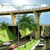
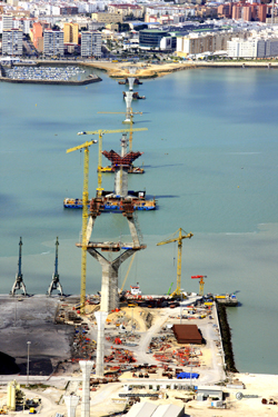
The new bridge is being built to improve access to the port; although its location is perfect for marine traffic, land access is tightly restricted by the fact that the city sits on a narrow spit of land connected to the mainland by just two main roads.
It will offer a direct route to the port and the city across the Bay of Cadiz, but its prominent position and the sensitive environmental location in which it is being built have demanded careful consideration in both the design and the construction.
Development of the New Cadiz Bridge project was carried out by Spanish consultant Carlos Fernandez Casado, led by Javier Manterola. Work began in 2007 and completion is currently scheduled for autumn 2012. The link has 37 spans ranging from 32m to the main cable-stayed span of 540m, and is just over 3km long including the approach viaducts on both sides.
The cable-stayed bridge crosses the main shipping channel, providing a navigational height of up to 69m above sea level. But the proximity and importance of the shipyards meant that the designers also had to consider the possibility of assuring access for oversize vessels or unusual structures such as oil rigs. The only way to do this was to provide a channel that had unlimited headroom – usually offered by a bascule or similar movable span.
The unrestricted span forms part of the western approach viaduct, and a number of alternative solutions were considered for its development, with two in particular meriting full comparison.
The first option was a conventional, 185m-long movable span, which would have a total length of 245m and a clear width of 140m. The second option was a simply-supported, 150m-long removable span which would have to be lifted out to provide the clearance.
Advantages and disadvantages for each option were carefully considered, focusing mainly on the lifetime costs, construction difficulties and operability and maintenance requirements. The main advantage of the conventional movable span was the reduced time taken to open and close it, but given that the span was intended to be used in exceptional circumstances only, operation time was a less important factor than the other ones under consideration.
As a result, the economy, lightness, feasibility and reduced maintenance of the removable span tipped the balance in its favour. This choice was fully justified in 2008 when a decision was taken to add a two-track light rail system to the structure. Despite the fact that work on the foundations had already started, the design of the bridge had to be adapted to make it wider and able to resist higher dead, live and seismic loads while at the same time avoiding an increase in self-weight.
The resulting bridge is 33.2m wide on average, and longitudinally it has been planned as four distinct deck types. The west approach bridge has nine spans which vary in length from 50m to 150m and will be a continuous, composite structure built by launching. This section will include the removable steel span of 150m length. The main bridge is a 1,180m-long cable-stayed structure which has a main span of 540m and side spans of 200m and 120m at each side; the deck is of composite steel and concrete construction with a constant depth of 3m. On the east side, there is a 1,183m-long continuous prestressed concrete deck on spans ranging from 75m down to 32m in length.
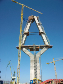
Of the two main bridge towers only one is built in the water – the other is located on land. The main towers sit on single-leg piers which split into two sections to form a diamond-shaped superstructure around the deck, and then join back into a single tower where the cable anchors are located. They rise to a height of 185m above the water level. A total of 176 cable stays support the deck, arranged in two planes of semi-harp formation. They will be anchored into 44 steel anchor boxes cast into each tower.
Construction work began in 2007 by main contractors Dragados and FPS. Innovative excavation solutions were required to carry out the construction of almost 500 deep piles both in the sea and on land for all the piers, towers and abutments, because of the upper fill and marine deposit layers ranging from 5m to 20m thick. Most of the piles are 2m-diameter piles with an average depth of 34m; a total of 48 were installed for the west tower foundation and a total of 56 for the east tower.
Steel pipe piles were used for the pile excavation, along with a polymer fluid for support. Third-generation polymers were selected rather than the more traditional bentonite because they are considered more environmentally-friendly, being biodegradable, and are easy and quick to prepare. They can also be easily corrected and stabilised on site if necessary.
A GPS-guided pontoon carrying a crane and drilling equipment was used to install the marine piles. The steel pipe piles had a corbel welded around the diameter with studs to connect to the bottom slab of the caisson within which the pile installation took place. All ten marine piers have pile caps that are either fully or partially submerged below the low water line – requiring a water-tight working area for installation. This was provided using steel caissons with composite lower slabs connected to the piles via the studs welded on the steel pipes.
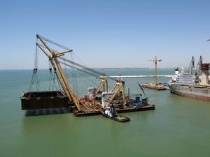
Caissons were floated into place using heavy-lift floating sheer legs and with a GPS antenna on the corner of each caisson. Positioning data was continuously received by the vessel, with images of the piles and the holes in the base of the caisson, to enable it to be placed with an accuracy of about 10mm. Once the piles and caisson were placed, the reinforcement and pile cap were installed and cured before the steel jackets of the caisson were removed to enable pier construction to continue as normal.
Care had to be taken to design the piles to resist tension and asymmetrical pressure resulting from uplift, waves and tidal currents. The interface between the steel pipe and the concrete was treated to increase its friction factor, using welded steel wedges. Some piles were also monitored using strain gauges.
Construction of the foundations for the western tower, which is built in water, involved the use of a watertight caisson 49m by 37m by 9m deep. The 1,200t caisson was floated into place along with 500t of steel reinforcement, by two connected floating sheer legs.
Within this caisson, the pile cap of 34m by 46m by 8.5m depth was constructed – while these dimensions might seem considerable, they minimised the size of base compared to what would have been required for a conventional double-leg A-shaped or H-shaped tower.
The geometry of the towers is currently being built up in five stages. High strength reinforced and prestressed concrete is used, ranging from 60MPa to 80MPa of compressive strength. The first stage involved the use of climbing formwork to build the lower single shaft. A hollow, variable hexagonal cross-section, with 1.8m thick walls was erected using self-compacting concrete in areas of dense reinforcement.
A special three-dimensional framework was then used as both falsework and