Closure of the launched deck on an unusual new bridge in Reunion Island has just been achieved. Helena Russell reports
At first glance there may be no obvious similarity between a modest composite bridge in Reunion Island in the Indian Ocean, and France's mighty Millau Viaduct, but scratch the surface and you will find that there are some very direct connections at work. Despite the huge difference in scale and the contrasting structural forms, the designs of the steel box girder decks on the two bridges are very similar - and because of this, steel contractor Eiffel has brought some of the construction equipment it used for the Millau Viaduct to this project.
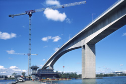
Although the new bridge over the Grande Ravine in Reunion Island is much smaller in scale than Millau, it has been very challenging to design and construct, and as Bd&e went to press, the crucial closure of the launched deck had just been successfully completed. The aptly-named Grande Ravine that the new bridge crosses is 320m wide and 170m deep, with very steep sides. The structure forms part of the Route des Tamarins, a 34km-long highway that is being built on the island. One of the central criteria for the design of the bridge was that all construction work had to take place from the sides of the ravine - the depth of the natural feature, plus the fact that it is a protected habitat, meant that it was impossible to use any kind of support from below.
The design, by Setec and architect Alain Spielmann (Bd&e issue no 44) was developed around the need to launch the structure from the two sides of the ravine, and as a result, the foundations and abutments, which act as a counterweight, are substantial. As Setec engineer Gregory Viel explains, some two thirds of the construction work that had to be undertaken is hidden from view, which made it difficult to see any progress on the early stages of the contract. Work started on site in June 2006 by contracting consortium Dodin/Vinci/Eiffel.
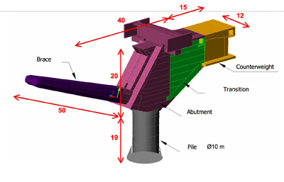
The structure consists of a 288m-long steel deck with orthotropic slab, which is hinged on two high-performance prestressed concrete braces inclined at 20° to the horizontal. The braces are cantilevered from counterweight abutments and maintained at their heads by external pre-stressing cables situated inside the deck. The abutments are founded on superficial footings at the rear under the counterweight and on a large diameter concrete pile at the front. The phasing of construction and the different structural behaviour before and after midspan connection, as well as the role of the provisional and final stays make it a very special structure, which is defined as having a limited and controlled arch effect.
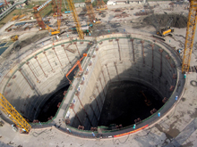
Two work sites were set up, one on each side of the ravine, and work has been continuing in parallel on the two banks, until they met with the closure of the deck at the end of October. Excavation of the pile, which was right on the edge of the ravine, was more like mining than construction, says Viel. It was excavated to exactly the finished dimensions - a 10m diameter hole with a 1m-thick wall, extending to 20m depth with a footing - since the environmental constraints required that the impact on the ravine was kept to the absolute minimum. Once this had been concreted, the counterweight was constructed.
The counterweight, which is located behind the abutment, was built in several stages, and had to be cooled during construction to limit the hydration temperature of the concrete to 65ºC, to eliminate cracking. On the footing of the pile, where cooling had not been implemented, the measured temperature reached at least 85ºC, explains Viel. The counterweight was formed of a hollow concrete box which was then filled with compacted soil from the site, to provide the required mass.
Meanwhile, construction of the abutment was also carried out in several phases, which were programmed in a particular order to limit the rotations imposed on the top of the pile. The abutment had two functions - as the support for the end of the steel deck, and also as the connection between the counterweight and the pile footing. It also houses the anchors of the prestressing cables for the permanent structure and the temporary cables for the launching of the deck; the top slab of the abutment is up to 2m thick. The bridge deck itself is a steel box girder, but rests on two concrete 'brace' structures, one on each side of the ravine, which are designed to enable the bridge to act as a 'limited arch' structure. The braces were built in 16 lifts, starting with the brace embedment at the pile, the formwork for which had to be installed using formwork supported on a beam that was suspended from the central zone of the structure.
The braces are designed to support their own weight, with the help of some 32 post-tensioning cables in each brace - the temporary cables that are installed across the top are to support the deck. Concrete works on the project were carried out by contractor Dodin, with the steel fabrication and erection by Eiffel - steel deck units were fabricated in the company's works in Lauterbourg, France, using the same equipment as was used for the Millau deck - although the Grande Ravine deck is just 20m wide, two-thirds the width of Millau.
The deck is made up of 24 sections, which range from 8.3m long to 13.9m long, and each unit was divided into 12 elements for shipping. Six elements form the central box structure - approximately 6m wide by 4m deep - and six more form the 6.95m-wide 'wings' on each side. The deck was manufactured at Eiffel's factory in Lauterbourg; after being taken by boat to Antwerp, the units were then transferred to a larger vessel and shipped to the island in six consignments, with the first delivery arriving in July last year (2007). Each shipment took about two months to reach the site. Assembly of the deck took place at each abutment - three assembly phases on each side - and was manoeuvred into its permanent position in six launching phases from each side. The first launch ended with the leading edge of the deck at the counterweight, the second movement took the cantilever edge halfway between the abutment and the head of the brace, and the third launch resulted in the deck edge arriving at the head of the brace. At this stage, with both the brace construction and the deck launch on the critical path, the third launch had to be timed to ensure that the brace construction had been completed before the launch began.
Casting of each lift on the brace structures was more complex than had been anticipated, with the density of the reinforcement slowing work down and preventing the contractor from achieving the three-day turnaround per lift that they had anticipated. All the same, they achieved a respectable four day cycle on the structure and closure of the deck took place at the end of October, ahead of the predicted schedule. As the leading edge of the deck cantilever approached the head of the brace, two specially-designed steel 'shoes' were installed on the top of the braces. These will support the bearings which will be installed on the shoes once the deck reaches its final position.
Viel explains that two shoes were designed for the top of each brace rather than a single, larger shoe which would have done the job just as well, but would not have left room to install a temporary jack to raise the deck ready for the installation of the bearings. Each shoe weighs 30t and a temporary frame had to be designed and installed to hold the shoes in place until the launching procedure was complete, and they could be welded into their final position.
A set of temporary stays wa