Few external signs exist of the extensive and complex work that is currently under way on the bridge construction. After the dramatic arrival of the first steel caissons in May last year, the lack of any immediately visible progress means that the public seems to have all but forgotten about the project.
All that is set to change this summer when the main towers of the bridge are expected to begin to rise from the choppy waters of the Forth Estuary, once construction starts to move upwards from the extensive foundation works. Despite the outward appearance, construction in the estuary is very much in full swing, with work continuing 24 hours a day to sink the cofferdams into place and prepare them for the tower construction.
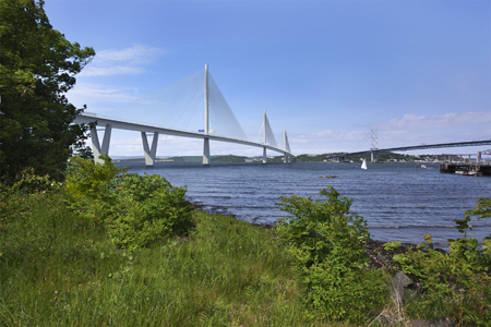
Visualisation of the finished bridge
As FCBCJV project director Carlo Germani explains, the contractor’s alternative proposal for the marine foundations was one of the major changes to the reference scheme. The original design that contractors were invited to bid on had piled foundations for the bridge, but the joint venture redesigned the structure with spread footings, in order to minimise the amount of marine work that was needed, and to exploit the contractor’s expertise to best effect.
A review of major bridge foundations and other offshore structures built by the joint venture partners was central to this decision to move to large diameter spread footings, along with the fact that similar techniques were used for the Akashi Kaikyo Bridge in Japan, which has even bigger foundations. On the north side of the estuary, what was initially proposed in the reference design as an approach viaduct has been redesigned as an embankment, and the contractor intends to launch the superstructure for the approaches off each bank.
All of this is intended to minimise the marine work that is required to build the bridge, as it is the marine work that carries the highest risk, not only in terms of safety, but also in terms of possible delays from poor weather. Once the foundations are complete, the main work to be carried out on the water will be transport of materials, and only the cable-stayed spans will be built from the water, Germani says.
The design team for the FCBC joint venture is made up of Ramboll, Leonhardt Andra & Partners and Grontmij, with the three companies each leading design on different parts of the crossing. Grontmij is responsible for the landworks, while Ramboll and LAP are designing the bridge itself.
Design JV project director Peter Curran explains that Ramboll is leading on the foundation and south approach bridge design, while LAP is leading on the cable-stayed bridge design. In addition to carrying out the detailed design of the bridge, the JV has an obligation to supervise, monitor, audit and certify that the work has been carried out in accordance with the contract, Curran says.
This role is being fulfilled by the DSR – the designers’ site representative team – which includes some of the members of the design team. As well as two teams on site, one overseeing the landworks and the other the bridge works, there are also staff based at the steel fabrication facilities to ensure that quality control is maintained. At the bidding stage, says Curran, the cost of the foundations specified in the reference design was estimated at a significant proportion of the overall cost, perhaps more than a quarter.
“We examined the foundations very carefully, as they are often the part of a project that gets overlooked,” he says. “We realised that there is a limited supply chain in particular for the large-diameter piles that were specified, and so we decided to develop the spread footing and caisson solution to eliminate this.”
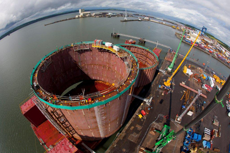
The caissons are 30m in diameter
A range of solutions and associated construction techniques has been adopted for the foundations of the bridge towers and piers, depending on the location of each, the ground conditions and accessibility. The central tower is located on Beamer Rock, an outcrop of rock between the two main shipping channels which offers a natural support for the cable-stayed bridge with its 650m-long spans. At this location the contractor first had to remove the top of the outcrop, blasting and drilling a 37m by 27m ‘pocket’ in which the temporary protection system could be erected. This system is essentially a sheet piled cofferdam formed out of L-shaped prefabricated units with concrete slab bases and 12m-high sheet pile walls. Ten of these units, each weighing around 90t, form the cofferdam – they were fabricated on land and then shipped out and lowered into place by the floating sheerlegs, then connected into the rock by means of ground anchors which were also used to adjust the height of each unit.
When Bd&e visited the site in early December last year, six of these units were already in place; by mid January all ten were in place and progress was being made on closing the gaps between the units with infill sheet piles and concrete stitches, before dewatering can be carried out. With the cofferdam pumped out, it will offer protection for the construction of the concrete base, ahead of tower works beginning in the summer. The sheet piles will be removed once the tower rises above the water level.
At three of the main bridge supports – the north and south towers of the three-tower cable-stayed structure and the first pier adjacent to the south tower, huge steel caissons are being used. These enormous double-skinned structures, the biggest for the south tower foundation rising to 30m in height, and with a diameter of 30m.
.jpg)
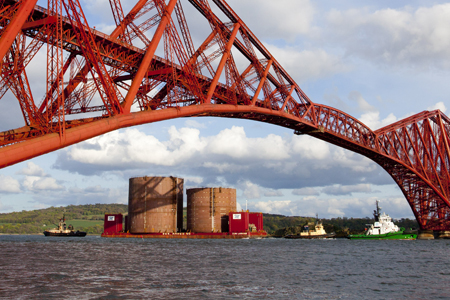
Arrival of the first caissons, which were brought by barge from Poland
These were fabricated in Gdansk in Poland and brought to the Forth by semi-submersible barge. The first two arrived at the site last May, making quite a spectacle as they sailed under the Forth bridges on a bright and sunny day; by comparison the arrival of the third later that year went unnoticed. The main caissons consist of two parts – the lower section, which is permanent and formed of a hollow section wall, and the upper, temporary section which is a single-wall sheet pile with the main purpose of offering shelter for the construction phase of the tower base.
The hollow section of the permanent caisson kept weight as low as possible – although for the larger caisson this was still some 1,200t – to enable it to be lifted by the sheerlegs. The hollow section was then filled with concrete and water as necessary to overcome its buoyancy and aid the sinking process. Although this ballasting procedure contributed to the sinking of the caisson, the main process aiding this part of the work is excavation below the cutting edge.
This is carried out by two excavators working simultaneously, explains FCBCJV senior engineer Christian Niemietz, and continual monitoring is used to control the tilting of the caisson as it sinks through the ground. “We use live monitoring to ensure that we always know w