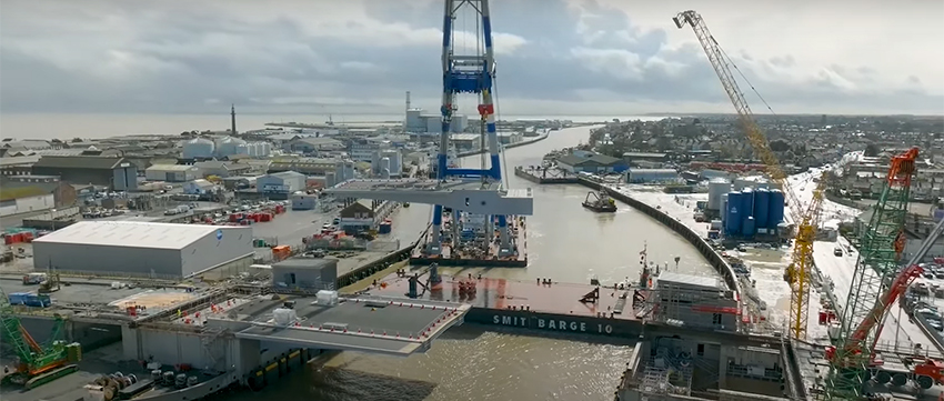

Construction of the main bridge connection on the new St Petersburg flood barrier required a major lifting operation. Leonid Blinkov, Vasilij Nikolayev and Igor Efimov report
Its location on the flood plain of the Neva River means that St Petersburg has been plagued by floods since the city was founded in 1703. It is particularly prone to tidal storm surge floods originating in the Gulf of Finland. In order to protect the city, a flood protection barrier which is more than 25km long is currently being built across the estuary. But the barrier will also incorporate a major highway, which requires several bridges across the navigation channels and sluices.
Construction of the barrier started as far back as 1980, but was halted in 1987 due to public concern that the barrier might have a negative impact on the environment.
An environmental impact assessment was carried out in 2001-2002 by Dutch consultancy Nedeco-WL Delft Hydraulics on behalf of Gosstroy, the implementing agency.
The EIA noted that the city has flooded approximately once a year for the past 300 years and about twice a year in the last 20 years, and concluded that the completion and operation of the barrier had been designed to meet relevant Russian and EU environmental, health and safety standards.
Poor water quality in Neva Bay was primarily due to inadequate waste water treatment in St Petersburg. The EIA showed that completion of the barrier will have no significant impact on the water quality in the Neva Bay and the adjacent Gulf of Finland. It will also improve the safety of navigation to and from the ports.
The detailed design of the barrier, which is more than 25km long, is being carried out by design institutes Lenhydroproject and Lenmorniiproject. It consists of eleven rockfill dams, six water discharge sluices to allow the water from the River Neva to pass through, and two navigation channels equipped with gates. The barrier also incorporates road bridges at each of the sluices, a road tunnel at one of the navigation channels, a lift bridge at the other and roads on the embankment dams.
The navigation channel C2 with the bridge crossing is on the northern ship channel. Whenever there is the threat of a flood, it will be closed using a lift gate in order to prevent water from the Gulf of Finland from entering the Neva Bay. The crossing at this location consists of a road bridge with a lift span at the navigation channel and two concrete viaducts at the sections connecting the dams to the bridge abutments. The main lift span can be raised by up to 9m to provide the required ship clearance of 25m.
The most complicated task during the construction of the bridge crossing was erection of the lifting span, which had to be raised to its final height of more than 22m. This section is a steel structure with orthotropic deck; it is 30.2m wide, 122m long and weighs 1,426t.
After consideration of various alternatives, engineers decided that the best option was to raise the structure into its final position using strand jacks. This solution required construction of substantial temporary works, to accommodate the strand jacks; steel portal frames were designed, manufactured and installed on the partially concreted piers for this purpose.
Subcontractor VSL was contracted to carry out this operation; it was the first time strand jacking had been used on a bridge project in Russia, and VSL was able to provide the experience, equipment and skilled personnel to perform the job.
The 1,483m-long bridge crossing of the north channel consists of the 122m-long main span, and two 206.5m-long embankment approaches. There is also a 474m-long access viaduct on each side of the main span. The bridge will be able to accommodate a six-lane highway with 0.75m-wide emergency lanes, and will be designed to a traffic speed of 120km/h.
The access viaducts are precast reinforced concrete structures with span lengths of 27m and 33m, divided into continuous sections of various lengths. The piers of the viaducts are built of in situ concrete. The main span is just over 30m wide and consists of two steel box girders with orthotropic plates. Each box girder has a width of 7.8m and height of 3.6m; the distance between the axes of the box girders is 11.6m. The lifting jacks were placed on temporary frames that were mounted of piers 18 and 19 of the bridge.
The process of erection of the steel structure involved raising an element weighing 1,426t to a height of more than 20m - from the assembly platform at -7m elevation to the design position at +16m level. This was the most difficult stage of the bridge construction.
A number of alternatives was considered for carrying out the lifting of the span. One was to use traditional hydraulic jacks with a capacity of 500t to carry out step-by-step lifting of the span. Temporary supports would be installed at each stage to provide support and safety during the lifting process.
Other options were to use belt elevators to carry out the lifting, or to bring in high-capacity cranes for this purpose. A number of considerations had to be taken into account during the comparison. The disadvantage of carrying out step-by-step lifting of large, heavy structures is that it is a very labour-intensive and potentially dangerous process that can take a significant amount of time to complete. With no belt elevators being available at the site, these would have had to be specially designed, and would require a large amount of temporary steel structures. This lifting process would also take too long to carry out.
Because of limited space at the construction site, there was insufficient room to use cranes with a high lifting capacity, and control of the superstructure during the lifting process was rather complicated. Use of cranes would not be able to provide the required accuracy of installation of the structure to the design position, particularly under the tight schedule.
Hence the lifting of the superstructure was carried out using hydraulic clamp hoists - known as strand jacks - mounted on steel portal frames at the piers. The lifting strands were connected to the main beams using tie-down devices. The strand jacks were installed on eight metal portal frames, which were mounted on piers 18 and 19, which had been partially concreted. Four portal frames were placed on each pier; the total weight of these portal frame structures was 260t.
Each portal frame had a cross-beam to enable installation of a strand jack at the +22.8m level. Portal frame pillars were equipped with supporting mounts at the +16.25m level to allow installation of supporting erection devices for the main beams once the superstructure had been lifted to its design position. Portal frames were connected to the piers with braces, and work platforms for servicing of the strand jacks, and locating pump stations were installed at the +22.8m level.
Four SLU-330 type strand jacks which each had a lifting capacity of 330t were installed on each of the piers. These jacks were connected to the main beams of the superstructure by lifting strands and tie-down devices.
Each strand jack consists of a double-action hollow hydraulic jack equipped with top and bottom wedge clamps and a lifting element formed of a batch of high-tensile wire strands, passing through the hydraulic jack and equipped with a dead-end anchor at the bottom.
The strand jacks installed over the middle main beams were equipped with lifting elements consisting of 27 strands with a bottom anchor, while those installed over the outermost main beams had 24 strands.
Each strand is 15.2mm in diameter and consists of seven wires of ungalvanised low relaxation steel.
All the jacks we