Heading inland from the city of Odawara, around 80km southwest of Tokyo, the scenery changes very quickly from urban construction to unpopulated wilderness where mountain roads thread a winding path across deep valleys and vertiginous drops. Across two of these gorges are the remaining links of a new major expressway currently under construction and which Bd&e had been invited to visit.
The subjects of the bridge tour were Nakatsugawa Bridge and Kouchigawa Bridge (‘gawa’ meaning ‘river’), two significant structures that are part of the final phases of construction for the Shin-Tomei Expressway (E1A). The new 253.2km-long expressway that is being constructed by operator Central Nippon Expressway Company (Nexco) will connect the cities of Nagoya and Tokyo. It shadows the existing Tomei Expressway, a 1960s built main highway that roughly follows the arching geographical contour of the south side of the island, but slightly further inland than the existing highway. When fully completed, the new highway will provide a more direct route than the existing one and one that will allow a faster driving speed of 140km/h. The new expressway was around 90% complete at the time of the technical visit, which was arranged by outgoing fib president Akio Kasuga to mark his last official meeting as association president with fellow fib praesidium members that had travelled from as far afield as Norway, Hungary and Switzerland to be there.
The tour began with Nakatsugawa Bridge, part of a 14.2km-long section of the new expressway section near the town of Matsuda, around 20km north of Odawara. The bridge was designed by Sumitomo Mitsui Construction and is being built by the same company, now acting as contractor.
The bridge connects tunnels running through the mountains on either side of the gorge and its location has severe access limitations that took five years to overcome via the construction of elevated access roads. The area being characterised by fault lines affected all stages of the project, including the bridge’s asymmetric design.
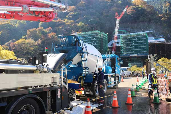
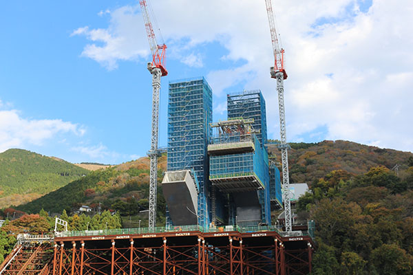
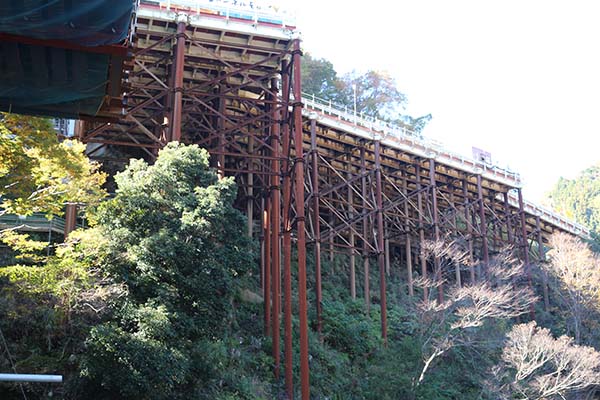 Elevated temporary structures help access the Nakatsugawa Bridge construction site
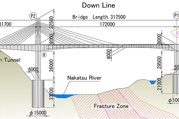
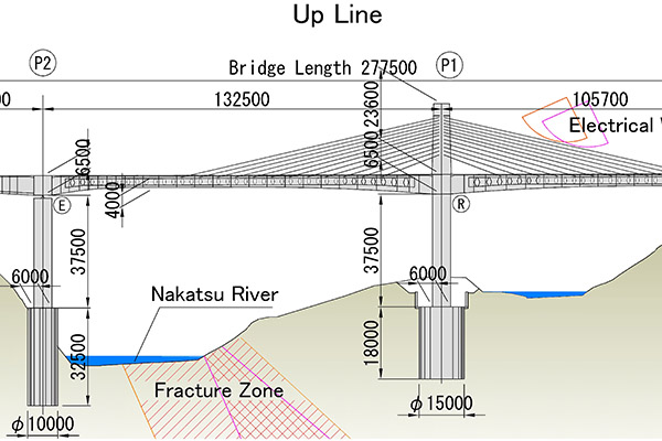
The crossing comprises two adjacent three-span extradosed structures with butterfly web box-girders. Each structure carries a single extradosed cable tower and these are located at opposite ends of the valley. The downstream crossing is 317m long and the upstream 277m, with corresponding span configurations of 81.7m+172m+61.2m and 37.7m+132.5m+105.7m.
Nakatsugawa Bridge is the sixth bridge in the world to feature so-called butterfly webs in its superstructure. This is a concrete construction element that weighs between 10 and 20% less than a similarly sized solid girder section and was invented and patented by Akio Kasuga, who as well as being the outgoing fib president is executive vice president at Sumitomo Mitsui Construction. The butterfly web, Bd&e readers may recall, resists shear force in a similar way to a double Warren truss and thus breaks down the shear force into separately transmitted compressive and tensile forces.
 Butterfly webs are used in Nakatsugawa Bridge in order to lighten the cable-stayed girder
The asymmetrical nature of the spans of each bridge structure and the location of the extradosed cable towers are the result of three main site constraints. First, the presence of the river and adjacent minor stream, which the structures were not allowed to touch; second, a fracture zone located at the valley floor, which made positioning of foundations problematic; and third, overhead electric cables on one side of the gorge that prevented the placement of both cable towers there, side by side. As a result, the cable tower on the downstream section had to be placed on the west, cable-free side where, unfortunately, its ideal position was occupied by the Nakatsu River and the fracture zone. In design, the tower therefore had to be shifted just above the foot of the mountain, only 63m away from the tunnel entrance above. This resulted in unbalanced cable spans, considering the 172m-long main span of the bridge.
 The asymmetrical nature of the spans and the positions of the extradosed cable towers are the direct result of the Nakatsugawa Bridge site constraints 1
 The asymmetrical nature of the spans and the positions of the extradosed cable towers are the direct result of the Nakatsugawa Bridge site constraints 2
The unbalance was addressed in two ways, firstly by having the lateral cable-stayed main girder extending 20m into the tunnel itself. And secondly, by making the 172m-long main span lighter through the use of butterfly webs, in contrast to the standard ‘solid’ web that comprises the tunnel side girder.
On the upstream branch, where no such constraints exist, the butterfly web is used in the main girder for its two longer spans, while a solid web is used in the shorter 37.7m-long span. On both structures the cable anchorages on the main girder are located at the edges of the cross section. They feature transversal precast ribs in order to increase stiffness of the 12.95m-wide upper slab. While these sections carry butterfly webs only on either side of the girder, an additional butterfly web is placed at the centre of the sections of the main girder where there are no stay cables and where the main girder alone is bearing the load.
The butterfly webs comprise 200mm-thick precast panels made of high strength steel fibre-reinforced concrete of 80MPa. While previous butterfly web bridges have all consisted of panels of the same size, this bridge has a large cross-section varying between 4m and 8m in height, the latter sized sections weighing in at 16t at their locations by the piers. Yasuyuki Ihara, Hadano construction office manager of Nexco, explained that due to their size, the large-scale butterfly sections could not be transported from factory 100km away to site in their completed form. Consequently, the elements that make these outsized webs are transported in three sections for assembly in a large tent on site.
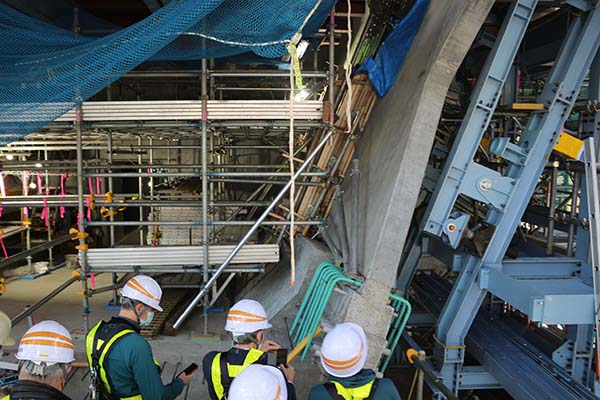 At Nakatsugawa Bridge the butterfly web is held in position by a steel frame until it is fixed in position
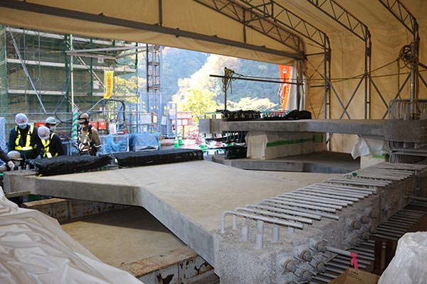 At Nakatsugawa Bridge the butterfly web is kept in a tent on site awaiting assembly
The three sections consist of one large rhomboid section and two smaller triangular sections that, when combined, form the characteristic butterfly shape. The large concrete sections contain prestressing steel strands 15.2mm in diameter and these are in alignment with the tension acting on the panels. The three sections are joined using mortar, grout and post-tensioning with 15.2mm-diameter steel strands. Each web takes seven days to assemble, after which it is quickly installed due to lack of storage space on site. During the visit it was observed that some sections of the concrete panels had different shading to others, but this was attributed to the fair faced form-finishing process which was applied only to sections that were to be visible.
 At Nakatsugawa Bridge the extradosed cable stays are anchored by a studded steel oval plate
During installation, the webs are lifted by tower crane onto a large 260t-heavy form traveller. Here, a slanted steel frame supports the web at the required angle until it can be permanently fixed to the lower and upper girder sections.
The cable towers are made of a combination of pre-cast (50MPa) and poured concrete (40MPa) sections using Sumitomo-Mitsui Precast Form for Earthquake Resistance and Rapid Construction (SPER), a method that aims to create high seismic resistance while speeding up construction. Here, precast panels with embedded hoop reinforcements are first installed, followed by steel reinforcement, after which concrete is poured to create a composite action.
 Concrete is poured to create a composite action at Nakatsugawa Bridge
For the tower anchorages of the 125mm-diameter extradosed cable stays, an innovate separate structure was designed. It consists of a 40mm-thick studded steel oval plate that, after placement inside the precast concrete forms, is then embedded with cast-in-situ concrete. In this way, the tension of the stay cables is borne by the oval steel plate while compressive force is borne by concrete. The horizontal component force due to the anchoring of the stay cable is transmitted to the oval steel plate via the bearing pressure of the concrete, while the stud dowels resist it. According to Kasuga, this anchorage design requires much lower amounts of reinforcement and PC steel than a conventional concrete anchorage, thereby reducing overall weight, while still allowing access to the anchorage ends for inspections. The nature of the new anchorage was the subject of some praise by fib members, especially as it was expected to reduce costs considerably.
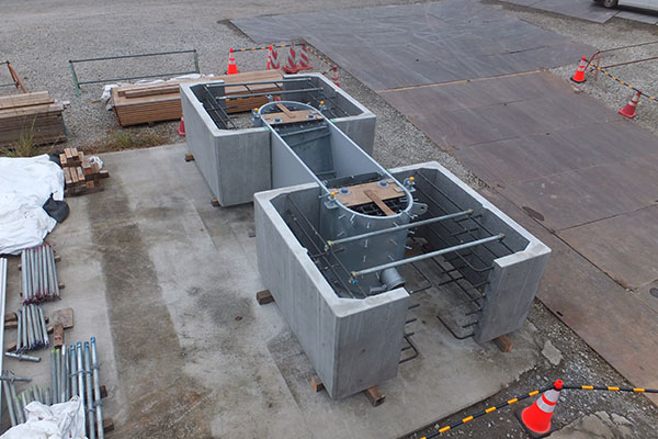
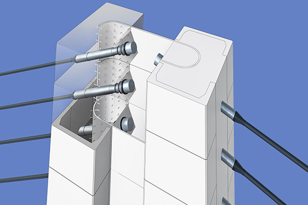 New tower anchorages for the extradosed cable stays at Nakatsugawa Bridge
As fib members walked around the cleanest and tidiest construction site that anyone had ever seen (“That concrete truck is cleaner than my car!”), Kasuga commented on how much the bridge had changed since its preliminary design, carried out by another company and featuring a standard box girder. “But after the contract was awarded to us, we identified the fault zone in the middle of the river. In the original design the pier was in the middle of the river, on the fault. So we redesigned and finally the structure was so unbalanced that we decided to use a lighter structure, and we recommended the butterfly web. The fault is at a skew, which is why it’s a bit asymmetrical.”
After observing the set-up of a form traveller about to begin the first section of the deck, the group headed around 10km westwards (as the crow flies) to the site of another structure that will form part of Shin-Tomei Expressway, this time taking the form of an arch bridge.
Kouchigawa Bridge spans Kouchi River east to west and consists of two parallel composite bridges with a central arch span of 220m. The north branch is 771m-long with eight-spans and the south one 692m long with seven spans. Pier height ranges between 75m and 88m. Both have lateral semi arches off the central span, these being steel and concrete while the remaining spans are PC box girders.
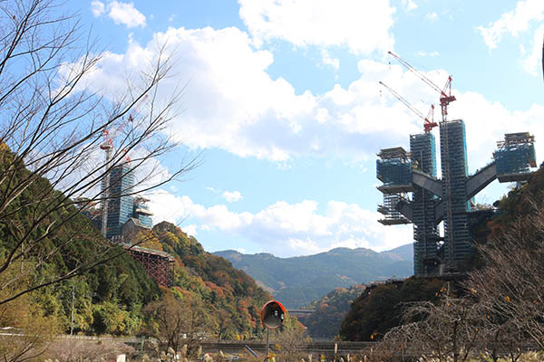 The site of Kouchigawa Bridge that will form part of Shin-Tomei Expressway, taking the form of an arch bridge
Whilst design had taken centre stage at the previous site, here the main challenge in focus was, without doubt, access. And during the briefing, the full extent of the types of access works that this part of the world can demand was revealed in full technicolour. Case in point was the construction of the piers for P2, one of the central arch pylons. In order to access its location and transport equipment and materials there from the access road, a 100m-long rail with a rail gauge of 15m had to be constructed at an angle of 41° to the mountain, necessary to carry a platform with a maximum load capacity of 90t. No less complex were the temporary works necessary to construct the two piers of central arch pylon P3. These required 230m of 7m-wide temporary access tunnels to be built into the mountain, in addition to a temporary tunnel yard and a massive elevated temporary deck.
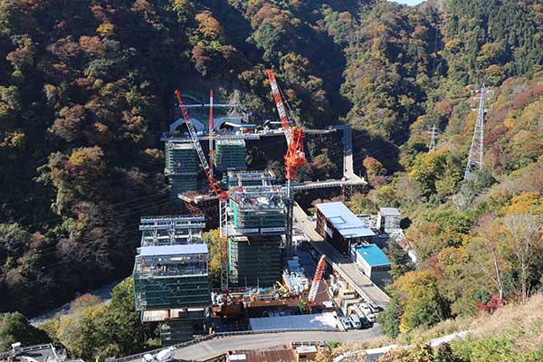
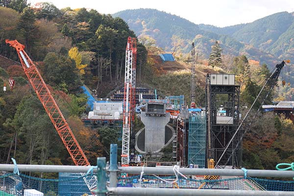
 At the Kouchigawa Bridge site the main challenge in focus was access
 At Kouchigawa Bridge access was achieved via temporary tunnels built into the mountain, a temporary tunnel yard and a massive elevated temporary deck
These works were needed because the main arch piers are supported by deep, large-diameter piles. These consist of double rows of steel H-girders placed vertically along the shaft walls, a method that – incidentally – replaced an original design consisting of multiple layers of rebar and in-situ concrete. In order to place these piles, a sizeable shaft around 17m in diameter and 33m in depth was dug using a combination of excavators and glory hole, with soil removed by conveyor belt to an adit below. As the shaft developed, cement mortar was sprayed on the wall, steel shoring ring and wire mesh placed and then secondary mortar applied.
More conventionally challenging perhaps is the construction method for the piers, which are being built using a combination of precast pier walls, rebar cages and concrete pours, the latter taking place after four such sections have been stacked on top of each other. To build the arch springs, a large temporary platform fixed on the pier itself was first constructed, from which sections of precast panels and rebars could be erected by chain block. Each arch half consists of 16 6-7m long segments and they will be constructed using the balanced cantilever method, in tandem with the bridge deck, to which they will be attached by cables. The deck consists of steel girders overlaid with precast floor slabs with integrated parapets.
During the briefing, fib delegates enquired as to why some of the cables used to secure the cantilevers of the arches during construction were to remain after completion of the bridge. The answer was for seismic reasons, which one professor hazarded would arguably make the structure a hybrid arch/truss structure.
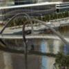
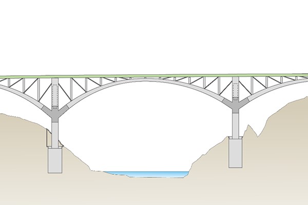 Drawing of the completed Kouchigawa Bridge, including cable stays for seismic protection
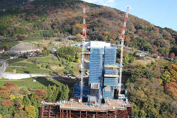
Walking to site and then rising to near-deck height at the top of P3, 85m high, it was possible to see that work on the cantilever had only just started. The formwork traveller was in the process of erecting the fourth block of the cantilever, which came in at 220t in weight and 90-100m3 of concrete. Erection of the steel girders that will support the 220m-long deck were expected to begin next month (December), and construction was planned to be complete by March 2024 (“tight”, said one worker).
 View from deck height at P3 of Kouchigawa Bridge. The arch bridge will feature two parallel central arch spans 220m in length
Visit over, the return journey to Tokyo on the Shinkansen (also known as the bullet train) provided an opportunity to assimilate the sheer variety of bridge construction methodologies that had been observed in two very different bridges only a short distance apart. Arguably, the challenges posed by the landscape leave Japan’s civil engineers with little option but to embrace complex design and to adopt a highly meticulous approach to planning and construction. But such a view would not take into account the innovation that also features strongly in these works, and which perhaps reflects a belief that improvements can always be made, somewhere.