With the successful completion of a two-phase launch over Bordeaux’s main railway corridor, Pont de la Palombe’s opening early next year is set to improve connectivity between areas of the city that have historically been separated.
The project is part of a large-scale urban renewal project which is intended to regenerate land around St Jean railway station in Bordeaux. The focus is on pedestrian access and sustainable development of neighbourhoods, with particular attention on the quality of public space.
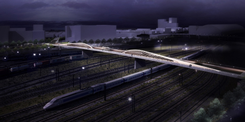
Rendering of the finished bridge (MMAI)
This central connective element which will unite neighbourhoods is regarded as a tool for dialogue with the infrastructure, the railway station and the railway tracks. The designers view it as a positive force, an urban service to the city, considering that the railway tracks form a ‘river’ — a physical barrier to urban redevelopment.
The bridge of La Palombe, which translates as Wood Pigeon Bridge, crosses the railway tracks about 200m south of the station of Bordeaux Saint-Jean. It will be the main connection to the new districts of Amédée Saint-Germain and Armagnac, which are currently being developed by the Public Development Agency of Bordeaux Euratlantique.
The static scheme of the structure is a continuous beam on four supports with spans of 66.1m, 65.5m and 66.1m, largely dictated by the location of the supports between the railway tracks. The structure had to be designed with consideration of the construction method, which involved the deck being launched over the railway.
In its permanent state, the superstructure consists of a box girder and a perforated steel plate intended to increase the stiffness of the deck over the bearings, allowing the depth of the deck to be kept to a minimum, and the necessary clearance over the railway tracks to be achieved.
During the launching procedure, the steel plates in the superstructure were designed to act with the launching nose, to limit the deformation of the structure at the maximum cantilever position.
The cross-section of the structure is asymmetrical to allow circulation spaces on the structure to be separated, using the superstructure to shield pedestrians and cyclists from road traffic. The highway pavement is directly laid onto the upper steel plate of the box deck, which takes the form of an orthotropic slab across the highway section, and a simple reinforced steel plate across the pedestrian section. The walkway is accommodated on a cantilever attached to the main box section.
The choice of the materials for the structure and in particular the treatment of the soffit of the bridge had to take into consideration the constraints relating to a bridge over a railway. The entire underside of the structure – both the multi-cellular boxes and the cantilevered pedestrian decks – are made of Corten steel in order to reduce maintenance and in particular eliminate any need for repainting, which is difficult in a constrained railway context.
Construction issues were considered in the design process from the beginning, with the launching rails integrated into the permanent structure of the deck. In order to limit the transversal redistribution of loads during the launch, two parallel girders of identical geometry were integrated into the soffit of the deck to serve as launch rails. They are of identical depth, and in elevation they are described by a circular arc of identical radius.
The design of the perforated steel plate was also guided by the distribution of loads. Its density is higher over the bearing to ensure the transmission of shear, and the perforations become larger towards the midspan.
During the design process, both the permanent and the temporary phases were integrated in the modelling of the structure. A linear finite element modelling of the entire structure was created using bar elements, but the transmission of loads between the main components, such as the box girder and perforated steel plates, was calibrated using plate elements. The global bar model was also used to determine the behaviour of the bridge during the temporary launch phases.
The structure was designed considering shear lag along the plates of the box girder as well as both local and global warping in the plates of the deck and the perforated stiffeners. Besides validating the bar model, the plate models were used for the detailed design of the steel elements – for example the local stiffening over the bearings – and also for the study of the transition of loads between the integrated launch rails and the main structure, during the erection phases.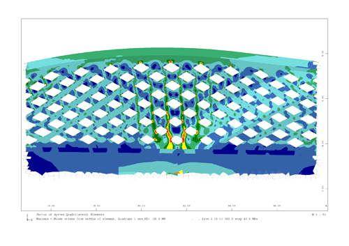
Diagram showing stress concentrations on the upper steel
The construction of the bridge was carried out by main contractor Bouygues Travaux Publics Régions France, steel fabricator Victor Buyck Steel Construction and foundation contractor Pro-Fond. Construction site supervision was by Marc Mimram Architecture Ingénierie working with Artelia.
Construction began in August 2016; before the first sections of the steel structure arrived on site, the contractor had to build all the supports, including two within the railway environment, and two abutments, one at each side of the railway domain. A launch pad of fill had to be built on the west side of the site, along with a temporary steel structure to support both the assembly and the launch of the bridge.
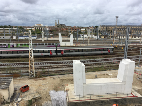
The bridge has to straddle the railway lines (MMAI)
The first pieces of steel arrived on the site in August last year; the site compound at the eastern end of the bridge was only 150m long, so in order to have sufficient space at the back of the launching pad, assembly of the deck had to be done in two phases, with the first launch taking place in between the two.
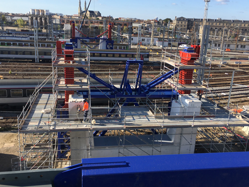
Temporary launching pier support (MMAI)
The first phase of the construction involved assembly of six segments, to a total length of approximately 130m, after which the first launch was carried out. This involved around 100m of deck, including the temporary launching nose, being pushed forward onto one of the supports in the rail corridor.
The deck structure was divided into ten sections in the longitudinal direction, and each section was divided transversely into five parts. Sections ranged in length from 16m to 22m with a width of up to 4m and unit weight of between 16t and 72t. Including the perforated steel superstructure, no less than sixty sections in total were delivered to the site by special convoy.
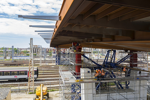
Launching procedure under way (Eric Robert Photography)
The second assembly phase began at the start of this year and the second launching operation took place in May. During the second phase, the deck had to travel 130m across the railway corridor from the intermediate pier to the abutment at the other side. This distance was travelled by the 2,000t structure in just over 12 hours.
The deck assembly was pulled forwards using a strand jack at the rear abutment which was attached to a launching nose on the rear of the deck assembly. For the second part of the launching operation, which was downhill, a restraint system was also incorporated at the rear of the deck assembly to enable full control of the structure throughout the operation.
This braking device also served as a back-up system which could roll back the bridge if necessary. It was anchored by a solid concrete pillar behind the launching platform. This operation involved the use of an automatic servo-controlled computer system.
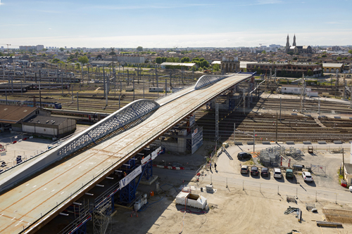
Aerial view of the launching procedure (Eric Roberts Photography)
During the launching, the deck was subjected to variable stresses and deformations. The supports were designed to act as ball joints and enable the rotations put into play on the launch bearing supports to be accommodated. The lateral guides integrated in these launch bearings ensured the structure was guided transversally during all the phases of the procedure.
To allow the structure to move, Teflon pads were introduced manually between the underside of the Corten steel structure and the stainless steel plate of the bearing. Thanks to this system the coefficient of friction was less than 5%.
To support these launch bearings and allow the launching operations, temporary steel structures were positioned next to each permanent concrete structure and anchored to the top of these supports.
A 29m-long launching nose was installed on the front of the deck. This structure, which was made of welded box beams with wind-bracing, allowed distortion, as well as stresses, to be reduced thanks to a reduced dead weight compared to the deck. It also allowed the structure to touch down on the temporary launch bearings in a horizontal alignment, thanks to the curvature of its lower flanges which reduced friction and consequently the transverse forces on the bottom structure.
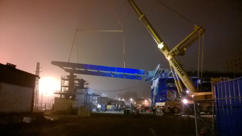
The launching nose being installed
All these temporary structures – front and back launching nose, launch bearings, and so on - were designed in accordance with railway regulations as first-class temporary structures and therefore had to give the same guarantees as permanent structures. The temporary structures were designed to allow the launching operation to be maintained even in winds of up to 80km/h. Once the launch was complete, a lifting operation had to be carried out to bring the deck up to its permanent position. Due to the curved profile required for the launch, the deck had to be lowered by 400mm at the rear abutment, 1.6m at the first support, 2.8m at the second support and finally 4m at the front abutment.
A tower jacking system was implemented at the rear and intermediate supports, with a classic jacking procedure being sufficient at the front abutment. Each tower was equipped with eight cylinders or jacks with 100t capacity connected to the same hydraulic circuit.
The 200mm-deep steel beams on which the temporary bearings were supported were progressively lowered, by applying a 200mm stroke to the jacks. After each operation the jacking head was slowly lowered.
The vertical descent was conducted by alternating between the front abutment, and quasi-simultaneously at the intermediate supports. Once the deck was at its final level, and the permanent longitudinal fixity of the structure was activated at the appropriate pier, the final descent could then take place at the rear abutment.
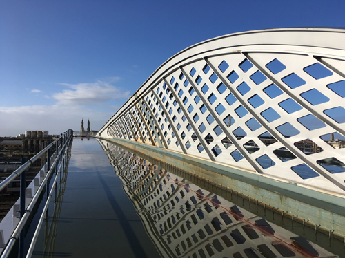
(Eric Roberts Photography)
The bridge is now in its permanent position and finishing works are ongoing; this phase is expected to continue until the end of December. The access ramp on the Armagnac side is due for completion in March 2019, and the final project for the Amédée district, which includes an access ramp and another steel bridge to link to street level, is also in the finishing stages.
Razvan Ionica is associate director and Thibaut Dubegny is specialist bridge engineer at Marc Mimram Architecture Ingénierie