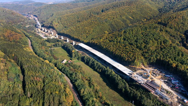
The 4.36km-long Kriván-Mýtna Viaduct is currently being constructed in an environmentally sensitive mountainous region between the cities of Kriván and Mýtna, around 300km northeast of Bratislava. The new crossing is a design-build project of Slovakia’s National Highway Company (Národná Dialnicná Spolocnost) and is being constructed by the R2 Kriván Mýtná joint venture formed by Doprastav, Strabag, Eurovia SK, and Eurovia CS. Viaduct design is by Stráský, Hustý a Partneri and the project design team is led by senior bridge designer Libor Hrdina.
The 27.5m-wide bridge runs through the beautiful valley surrounding Krivánský Creek and carries both directions of the 24.5m-wide R2 expressway. The entire length of the viaduct presents a uniform architectural and structural solution with a semi-integral structural system.
At its ends, the viaduct rests on mountain slopes while its central portion crosses an existing highway and river creek at several locations. As a result, while side-span lengths are either 60m or 70m long, the spans of the central section above creek and highway fluctuate in length between 70m and 150m at the skew sections.
During the development of the structure, it became evident that the viaduct’s side spans could be either cast in place using movable scaffolding or, alternatively, be incrementally launched, while the central parts would require balanced cantilever construction.
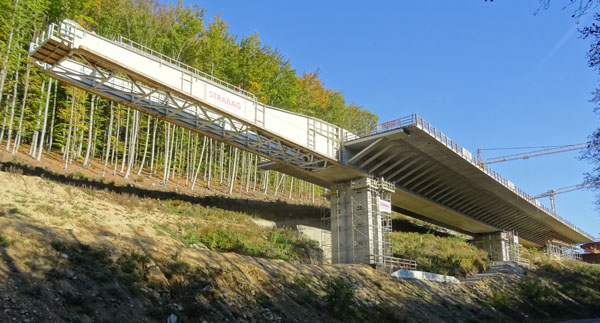
From the very beginning of the design phase, the optimum solution appeared to be a single structure formed by a spine box girder with large overhangs, all supported by narrow piers (see below).
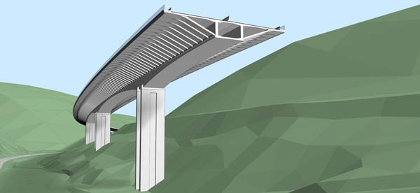
Such a structure would require minimum excavation at the steep slopes and would present a transparent series of support elements that minimally disturbed the beautiful countryside. However, the designer had to prove that it would be possible to transfer all traffic to the opposite carriageway during periods of road repair and maintenance. Along the whole viaduct length, the width of the box girder’s lower slab is 6.5m, and each of the side overhangs is 10.25m in length.
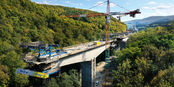
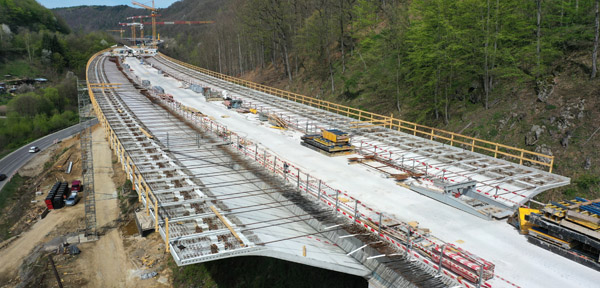
The construction of the viaduct started in 2021 and it is being built incrementally to minimise the weight of movable scaffolding. The sequence begins with the casting and longitudinal prestressing of the spine box girder, after which precast struts are installed for the overhangs. The deck slab, which includes stiffening at the edges, is progressively cast using simple formwork supported by the same precast struts (as shown below).
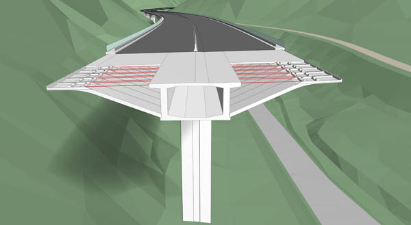
When the deck has been transversally prestressed, the external cables are installed inside the box girder and the whole structure is longitudinally prestressed.
We used this progressive construction technology as early as 1984 for the construction of our first cable-stayed bridge. It was built to carry the D11 expressway across the River Elbe near the city of Podebrady in the Czech Republic. The methodology was also used in 1993 for the Lanový Bridge that forms part of Prague’s City Circle Road. Following a hiatus, a renaissance of this technology took place in 2010 when the 957m-long Hostovsky Creek Viaduct was constructed near Nitra in Slovakia. Thereafter, it was used on four Slovakian expressway viaducts with a total length of 1.2km. As no structural problems were ever reported, this technology was selected for the viaduct that is the subject of this article.
The structure was designed as an integral structure to simplify structural details and to eliminate bearings. The piers are formed by twin slender walls that guarantee the stability of the cantilever structures during construction while also allowing large longitudinal movement of the completed multi-span structure. They not only support the cantilever structures but also support the equipment used to construct the spans at each end of the viaduct, specifically the cast-in-place pier tables bearing the front legs of the overhead movable scaffolding.
The piers in the end sections of the viaduct consist of two 6.5m-wide, 0.8m-thick facing walls that are 1.5m apart. In the middle portion of the viaduct (built with cantilever construction), the piers are formed by facing walls that are 7.5m wide, 1.25m deep and 4m apart.
The viaduct is divided into eight expansion sections. The twin walls situated in the middle of the expansion sections are frame-connected with the deck and footings, while the walls at the ends of the expansion section are hinge or frame-connected with the spine girder and footings, depending on the position and height of the piers. The hinges at the footings are immobilised during deck construction.
The foundations of the bridge structure reflect the very different geological conditions along the length of the route, with high-quality ground conditions alternating with low-quality bedrock. While most foundations are formed by micro-piles, some supports are also founded on large-diameter piles or on spread footings. Jet grouting improves the poor-quality bedrock for two piers situated close to the creek.
The expansion joints (see below) between the first and second expansion sections and between the fourth through to eighth sections are placed in the gap between the sections’ end diaphragms, each of which is supported by a slender wall.
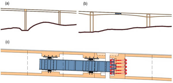
In the cantilever structures, however, the expansion joints are located in the middle of the shortest spans. Long term deformations of the adjacent cantilevers are reduced by the use of steel girders that are inserted into the spine box. In contrast with the solution developed by Jean Muller, in which steel girders are inserted in adjacent cantilevers, an arrangement was used that I had previously developed for the construction of the Benicia Martinez Bridge across the Sacramento River in California.
In this instance, the expansion joints/steel girders are fixed into the midspan diaphragm of one cantilever and inserted into the box cell of the adjacent cantilever, where the girders are supported by neoprene bearings on the span diaphragms. As proof of the proposed solution was requested by the client, the California Department of Transportation – the owner of the Benicia-Martinez Bridge – provided a letter of a recommendation confirming that the bridge completed in 2007 was regularly inspected and that the bridge and its hinges functioned without any significant problems, behaving according to design assumption. As a result, this solution was accepted for the Kriván-Mýtna Viaduct.
Advanced Building Information Modeling (BIM) methodology underpin the bridge’s design and construction, and a 3D bridge model includes the specific information requested by the contractor for all structural elements. Collaborations took place using CDE Trimble Connect.
Regarding construction, as previously mentioned the viaduct is divided into eight expansion sections. The first section is 681m long and consists of 10 spans 60m and 70m in length. The 3.5m-deep spine box girder is being incrementally cast, span by span, using formwork suspended by an overhead movable scaffolding system that includes so-called ‘organic prestressing’ to eliminate erection deformations.
The spine girder is longitudinally prestressed by internal tendons situated at the webs. These cables are coupled at construction joints located 17.5m away from the piers. When the overhangs are cast and transversally prestressed, the external cables situated inside the box are installed and post-tensioned.
The three expansion sections that follow the first section are 685m, 700m and 695m in length. The spine girder for these sections is constructed in symmetrical cantilevers starting at piers tables.
The lengths of the side spans are 80m and 70m. Due to local obstacles, the length of the rest of the spans varies between 100m and 150m. The depth of the girder at midspan is the same, 3.5m, while the depth at the supports depends on the span length. For span lengths of 140m and 150m, the depth is 9m, for shorter spans it is 6.5m.
The pier tables are 12.5m long and the segments 2.5m and 5m in length. The deck is longitudinally prestressed by prestressing tendons of a common arrangement. During cantilever construction, the cantilever tendons situated at the top slab are post-tensioned. After mid-span closures are cast, the span tendons are installed and post-tensioned. These tendons are supplemented by continuity tendons situated in the webs and overlapping at the pier tables. In addition to these tendons, external cables inside the box are installed and post-tensioned, an operation carried out once the overhangs are cast and the deck is transversally post-tensioned.
The fifth and sixth expansion sections are each 400m long. They consist of six spans in an arrangement of 60m, 4 by 70m, and 60m. Their structural arrangement and construction technology is the same as that of the first expansion section.
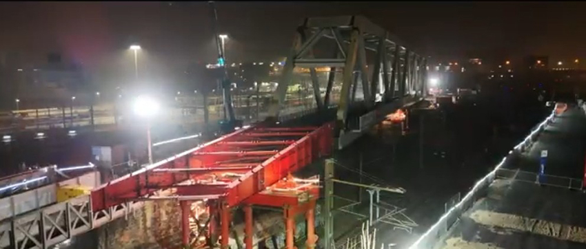
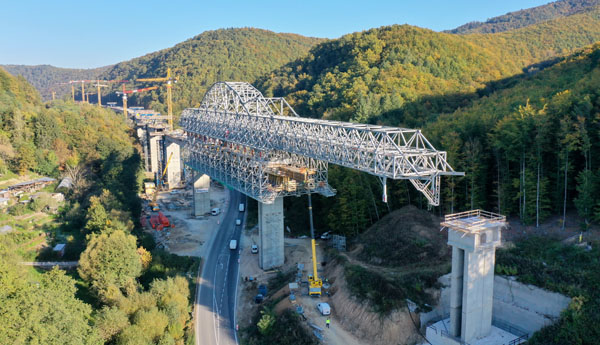
The seventh and eighth expansion sections are also 400m long and are formed by incrementally launched continuous girders of seven spans (50m, five by 60m, 50m). Since the box girder of each section has a different curvature in plan, they are incrementally cast and launched from a common central pier. The deck is initially launched towards the middle of the viaduct and, when completed, the launching nose and equipment are turned around. The deck is now being launched in the opposite direction.
While the deck of the incrementally launched section has the same shape as previous sections, the outer slab struts supporting the overhangs are substituted with individual bars. However, since the bars are situated at the same positions as the slab struts, the structure looks similar.
The contractor decided to launch the entire 27m-wide deck and therefore built a casting yard next to the expansion pier. For deck assembly, a platform was constructed that cantilevers transversally above the valley slope. The deck is created in two steps. First, webs and bottom slab of the spine girder are cast, then the top slab of the whole section is concreted and transversally prestressed. After that, the deck is longitudinally prestressed by straight tendons situated in the top and bottom slab and in the webs. When the whole expansion unit is launched, the external cables inside the box are installed and post-tensioned. The cables are deviated at the span and pier diaphragms, where they are also anchored. To reduce the number of anchors, the cables run through two to four spans.
The deck is being incrementally launched using traditional equipment formed by vertical and horizontal hydraulic jacks. The launching bearings are situated only on one wall of the temporarily stiffened piers. Static effects in the front cantilever are reduced by a steel nose formed by two plate girders of variable depth.
The launching nose had previously been used to launch a girder with greater depth than that of the current girder. To accommodate the height of the back of the nose, temporary concrete sections are used match the height of the rear of the nose, extending the girder’s webs backwards by 4m. The temporary sections are vertically and horizontally prestressed by prestressing bars to guarantee a safe connection with the girder and the nose. After the deck has been launched, the concrete hinges situated between the deck and piers’ walls are grouted and vertically prestressed by short cables anchored in the walls and the deck’s diaphragms.
Expansion Sections 1, 4 and 5 are being progressively cast with two overhead movable scaffolds. For the construction of the cantilever structures, ten pairs of travellers are being used. At present, the precast struts are being erected and the deck slab is being cast.
So far, the built sections of the viaduct confirm that the structure is not only structurally efficient, but also aesthetically pleasing. Although the viaduct forms a significant structure, its structural shape and the dimensions of its elements correspond to the scale of the surroundings, complementing them rather than overshadowing them.
Completion of the Kriván-Mýtna Viaduct is scheduled for 2025.
Jiri Strasky is technical director and partner at Strasky, Husty and Partners
The Kriván-Mýtna Viaduct
Client: Národná Dialnicná Spolocnost (Slovakian National Highway Company)
Contractor: R2 Kriván-Mýtná Joint Venture, formed by Doprastav, Strabag, Eurovia SK, and Eurovia CS
Viaduct design and engineering: Stráský, Hustý a Partneri
R2 Expressway Design: Dopravoprojekt