The Chenab Bridge project, which was launched nearly 18 years ago as part of the Jammu-Udhampur-Srinagar-Baramulla Rail Line (JUSBRL), has reached a major milestone with the ongoing launch of the 13.5m wide steel deck. When complete, the crossing will provide a major economic boost to the region, reducing the time taken to transport goods from the Kashmir Valley to New Delhi from two days to 20-22 hours.
The public authority delivering the bridge is Konkan Railway Corporation, which hired Flint & Neil (now COWI UK) as independent consultant at the project’s outset and selected a team of WSP Finland and Leonhardt, Andrä und Partner (subconsultant) for the design. The bridge is expected to have a lifespan of 120 years.
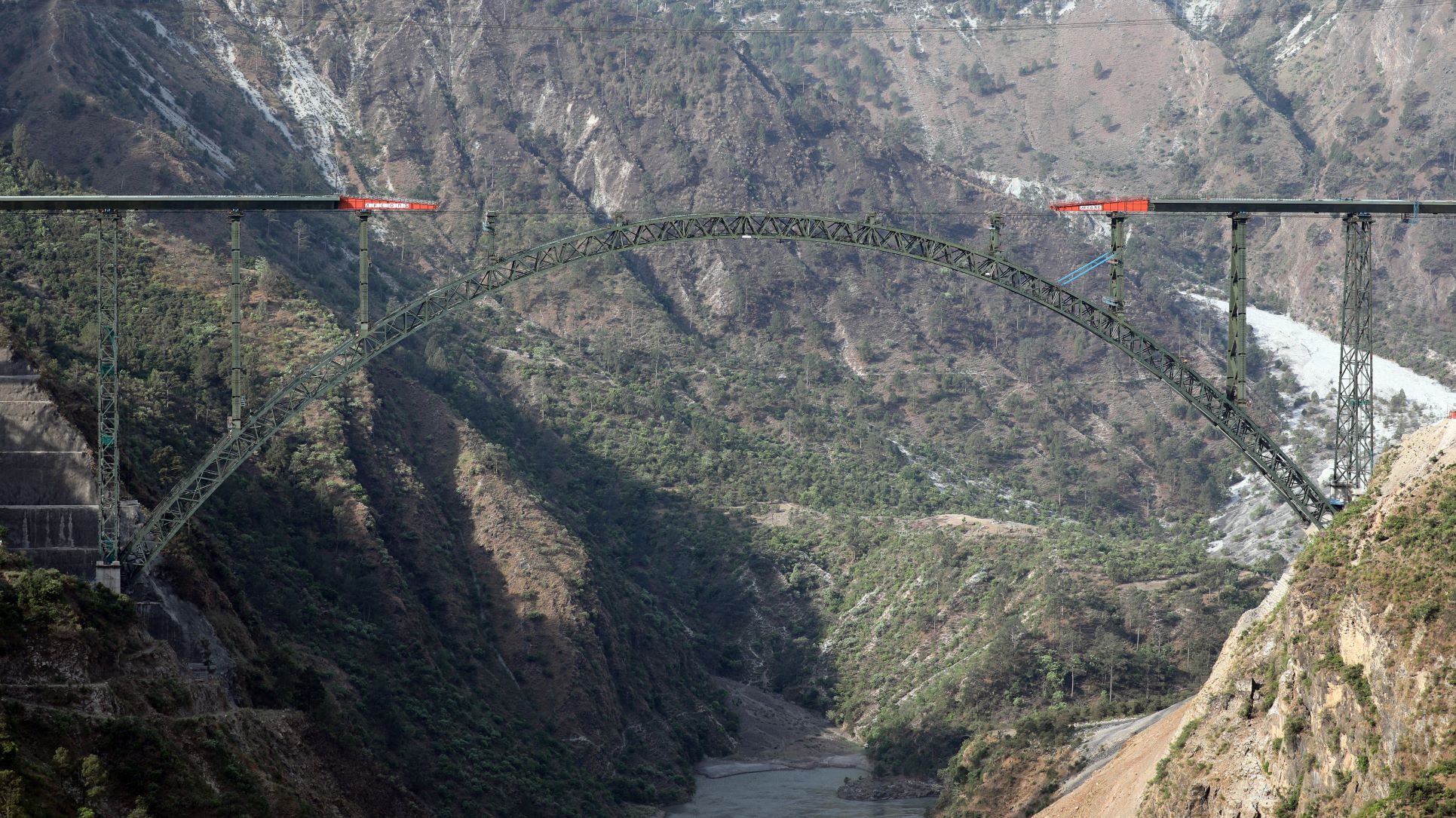 The steel deck sections are being launched from both sides of the rail bridge (Konkan Railway Corporation)
A long-span arch bridge is somewhat unique among Indian rail crossings, which tend to be simply supported structures; however, at this particular location, given the topography and steep valley sides, a steel arch was preferred from the outset, according to David MacKenzie, senior technical director at COWI, who has been involved with the bridge since the start.
The total length of the 17-span crossing is 1,315m, comprising a 530m-long approach viaduct supported by 11 reinforced concrete piers and a 785m-long deck arch portion. The latter consists of steel truss structures forming the arch, nine spandrel columns and seven piers of varying heights up to 140m.
For the designers and main contractor AFCONS Infrastructure, the site in the Himalayan foothills has presented huge technical challenges, not least the large amount of faults and shear zones as well as its location in a zone five seismic area – the highest on India’s zoning map. Numerous geotechnical studies were undertaken prior to breaking ground in 2004, and these found that while a lot of the top surface of the valley was significantly fractured and friable, the bottom layers of rock were strong and stable enough to accommodate the foundations of the arch and piers with some slope stabilisation.
Stabilisation measures included spraying fibre-reinforced shotcrete in two layers of 50mm (after installation of weep holes to avoid the build-up of hydrostatic pressure); installing rock bolts up to 11.5m in length perpendicular to the slopes at certain locations; and using pre-stressed bar anchors at abutting foundation S-40 and prestressed cable anchors at abutting foundation S-50 (Bd&e issue 106).
Reinforcement detailing has also been an important part of factoring the area’s seismicity into the design: “Seismicity is critical for the viaduct; very large bridge structures are less susceptible to earthquakes because they’re so big compared to the movement in the ground and the motion. Typically the viaduct piers are the ones most likely affected by seismic events, but that’s been mitigated in the design and through good detailing. The detailing standards are there to make sure that if there is an earthquake and there’s some yielding at the base of the pier, then the base of the pier is able to yield without significant damage and can be repaired afterwards,” MacKenzie says.
Not only is the bridge capable of handling an earthquake with an intensity of eight on the Richter Scale, but its critical members have also been designed for adequate redundancy. “Structural redundancy figures large in the design of the bridge such that it has been designed to continue to operate despite the loss of any part through accidental or unforeseen events. Large bridges represent huge levels of financial commitment on the part of national government and therefore the design must ensure that the loss of any element does not result in a disproportionate loss of the structure,” adds MacKenzie. “Through careful planning of the design, the designers have developed a very robust yet economical structure.”
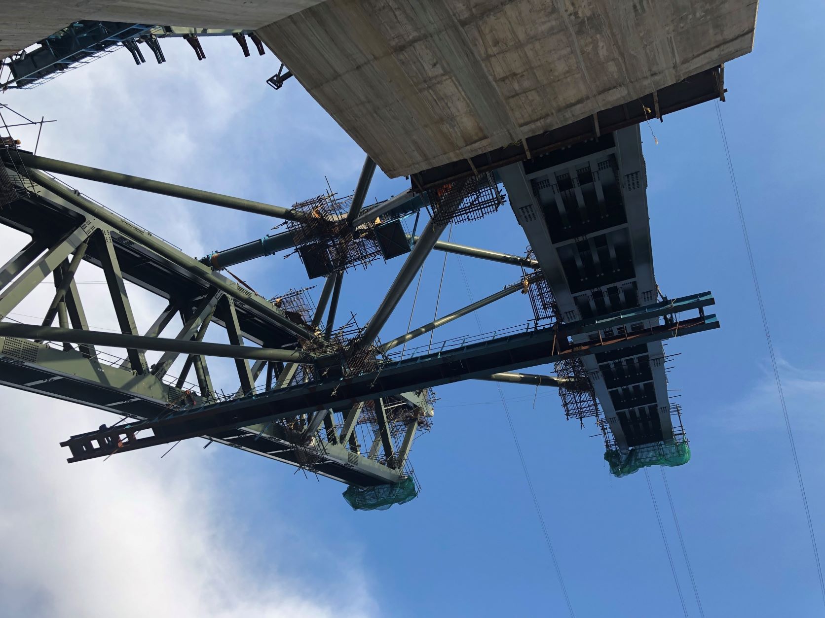 Arch chords contain self-compacting concrete to increase stiffness against wind loading
Wind is another governing factor in the design, and wind tunnel testing was conducted on a large topography model of the site to derive wind loads. “We have a very mountainous environment which generates a significant amount of turbulence so the wind profile which hits the bridge is completely different to anything else you might assume for other structures,” highlights MacKenzie.
“Another matter in this context was the height of the nearby mountains, which is in the order 1 km,” says Risto Kiviluoma, technology director, bridges at WSP. “A standard logarithmic wind profile is known to be valid up to around 200m depending on wind speed. We therefore needed to model the wind profile beyond that, up to around 1km.”
Testing on the topography model revealed up to 11° vertical inclination of the mean wind velocity and wide scatter of turbulence intensity of 7-55%, depending on direction. Section model testing was also undertaken, and the results were used to extract equivalent static wind loads, taking into account wind-induced dynamic actions of the bridge.
The structure has been designed to withstand wind speeds of up to 260km/h and trains will be able to travel in winds of up to 90km/h. Beyond the safe limit, sensors will activate signals automatically to stop trains transitting. To increase stiffness against high-speed wind loading, the chords of the arch truss sections were filled with self-compacting concrete, while the lateral bracing for the arch also comprises concrete-filled circular tubes. Filling with concrete removed the need to paint the internal surfaces or use stiffeners and offers superior corrosion protection. The outer arch elements taper from 30m at the springing to 10.5m at the crown to improve horizontal stability.
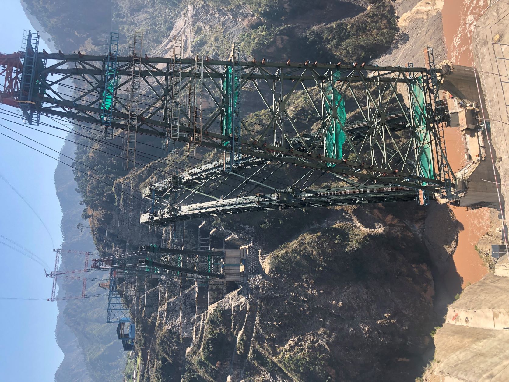 The arch sections were built outwards to a free-cantilever length of up to 48m
Given the bridge’s location in an isolated part of India, access has been another major challenge, and a road network has been created to help bring the manpower and equipment needed to execute the project. While one 15km road was initially needed to provide site access, a network roughly 200km-long has since developed, accompanied by upgrades to the local water, sewerage and electricity services. “This project has brought a lot of money and wealth into the region with all the associated infrastructure required,” says MacKenzie, who recalls the arduous journeys required to site along rocky mountain passes in the project’s early days.
The logistical challenges, combined with the need to fabricate some 25,000t of steel structures, meant it was deemed more efficient and cost-effective to undertake as much steel fabrication on site as possible. To this end, fabrication units and paint shops were constructed at four different locations on site – three north of the valley and one to the south – and more than 85% of steel fabrication has been conducted at these locations. The workforce also has a local flavour, with 60-70% of those hired to build the bridge recruited locally and trained in welding training centres on site.
All steel structures were modelled in Tekla to help ensure the compatibility of members during erection. To enhance accuracy further, the sections making up the arch, spandrel columns and piers were trial-erected prior to final installation. All the joints between the bridge’s steel sections, apart from the deck, are bolted, with the entire structure requiring around 600,000 bolts.
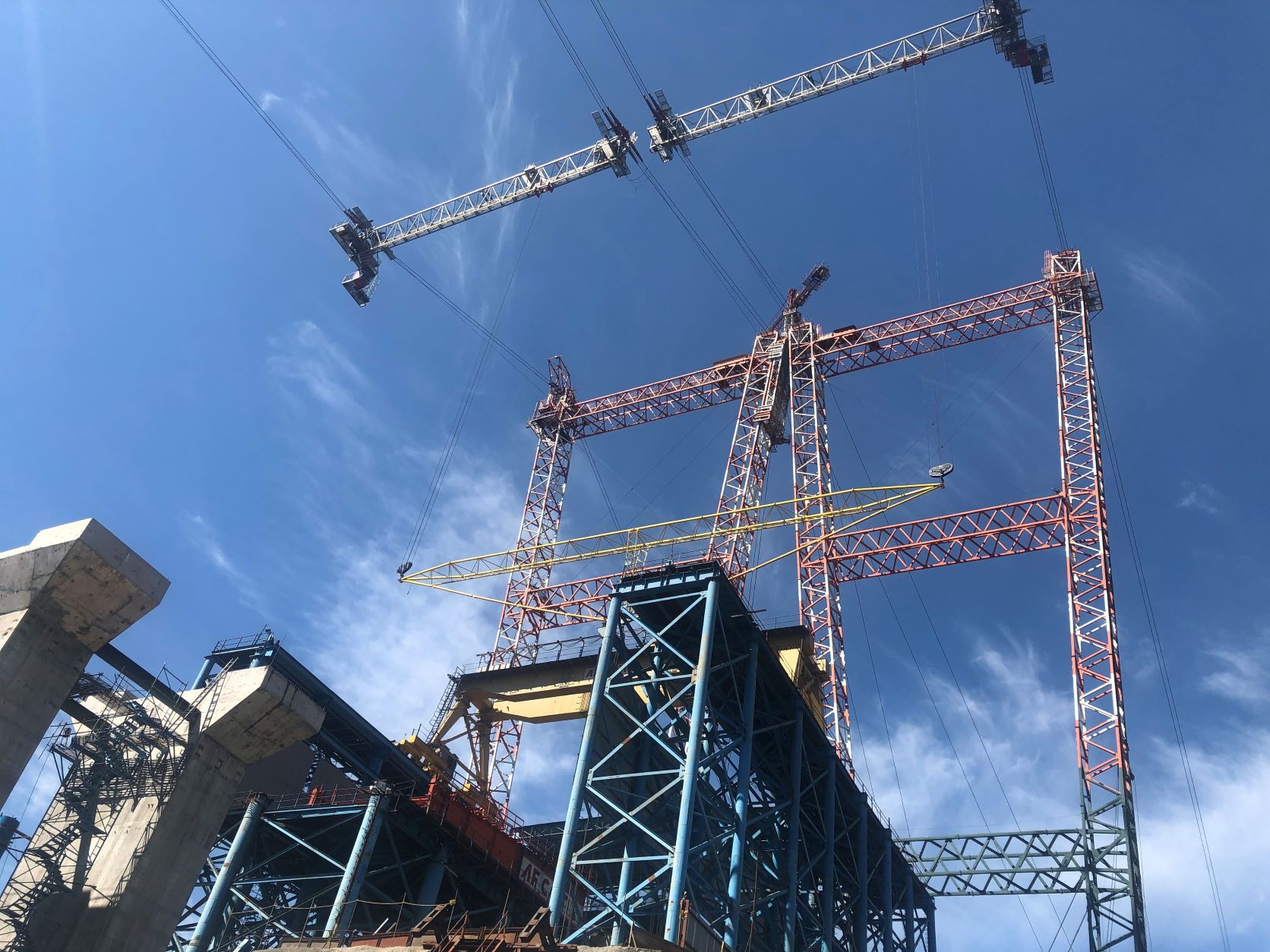 Two cable cranes provided a span of 915m and a combined lift capacity of 37t
Key to the construction programme was the installation of two cable cranes, which are among the largest ever built. The cable cranes provided a span of 915m and had an individual load carrying capacity of 20t and a combined capacity of 37t. “The advantage of that is that there were very little other temporary works required, but a lot of effort had to go into the design of that crane to make sure it would work and keep on working, so reliability was important,” says MacKenzie.
The deck sections have been welded together at the site workshops in sections measuring 8m in length and launched from both sides of the valley. Since the approach viaduct has a constant radius curve along its length, it was designed with temporary bearings to facilitate its launching. These were eventually replaced with permanent bearings and the approach was finished in 2017.
Mageba supplied 22 Reston-spherical bearings and 38 Lasto-block elastomeric stopper bearings for the bridge. The spherical bearings are free sliding and designed to carry vertical loads of up to 14,160kN while the elastomeric stopper bearings are designed for horizontal force of up to 5,100kN. The bridge also has three expansion joints: one at either end of the 785m-long arch portion of the bridge and another at the first pier on the approach viaduct.
The arch was erected using the cantilever method, with each section weighing up to 35t lowered into position using the cable crane and then bolted into place. The sections were built out to a maximum free cantilever length of 48m, corresponding with the horizontal distance between spandrel columns. At these points, the cantilevering sections were temporarily supported using stays attached to temporary steel works built on top of the piers at the abutting foundations, with backstays anchored to the ground.
Arch closure was achieved in April 2021 and followed by construction of the spandrel columns, which consist of cross braced truss sections with box members. Jacks and launching guides on the piers are being used to build the arch portion of the deck.
Grade E250C steel has been used for the deck superstructure to retain sufficient ductility in sub-zero temperatures, while Z-grade steel was used for the arch to provide enough thickness to prevent lamellar failure. Repainting of the steel elements will be required roughly every 15 years.
The installation of the bridge’s two rail tracks is expected to be completed by the end of this year.