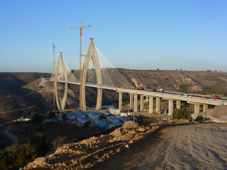
A new bridge in Morocco which opened to traffic at the end of last month (July) has created a new landmark for the country as well as setting a new record for the longest span cable-stayed bridge in Africa.
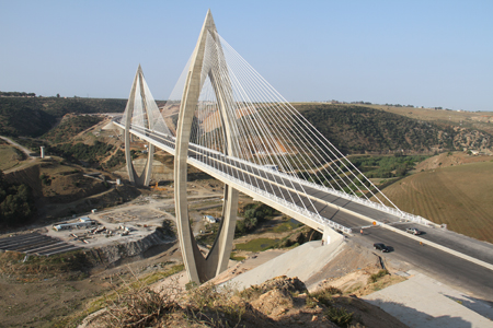
The dramatic structure has a main span of 376m and back spans of 183m, and forms part of the 954m-long crossing of the Bouregreg River. It is formed of two distinct parts: a two-tower cable-stayed bridge which is 745m long, and a five-span simply-supported beam-and-slab approach bridge of 209m.
The bridge will carry the highway bypass of the city of Rabat, and is part of a 41km-long dual carriageway motorway being built by the National Motorway Company of Morocco (ADM) on behalf of the Moroccan government.
Among the bridges on this section of the motorway, the Bouregreg Bridge was singled out for special attention by ADM (Bd&e issue no 73). The client was particularly keen to build a bridge with a strong and dramatic aesthetic; concept design for the structure was carried out by consultant Setec TPI with architect Strates, and detailed design by Egis and BRDI. Contractor is Covec MBEC.
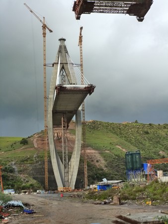
The concrete towers have a distinctive shape and are split into four legs across the majority of their height. They were constructed in 43 lifts of 4m height, with a 12m-deep concrete cap. The first 36 lifts were built using climbing formwork designed by Doka and comprising three platforms, which were moved upwards by the action of hydraulic jacks. Among the various construction constraints and construction difficulties, the main issues were the special architectural features of the towers which required adaptation of the formwork for each lift, in order to follow geometric variations, as well as the difficulty of fixing the dense rebar which is more than 250kg/m3.
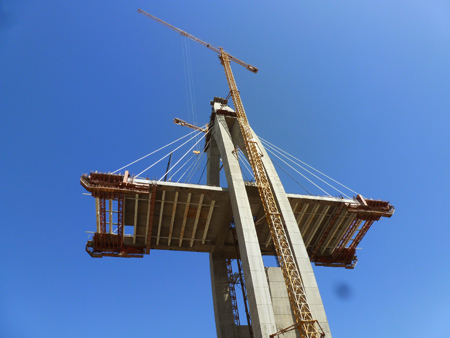
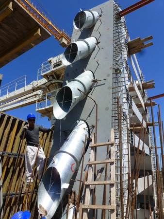
The joint between the tower and deck was made by transverse prestressed concrete elements which connect the four legs. The upper anchors for the stay cables are located in lifts 38 to 43 of the tower, and take the form of a box structure made of S355 and S460 steel. The 25m-high, 300t anchor box was divided into six separate sections for erection, which were easier to position than a single unit. The box was then encapsulated in thin cast concrete walls to maintain the architectural appearance. The positioning of these box girders at the top of the tower required very tight precision – a tolerance of 1% - to ensure correct orientation of the anchorages for the stay cables.
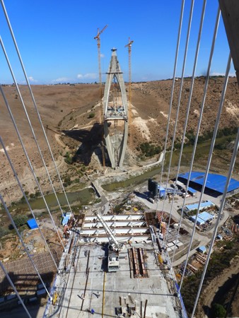
The deck passes through the legs of the towers and is simply-supported on the piers. Two planes of 20 pairs of stay cables are attached to each tower, in two lateral layers. These cables are anchored at the deck at 8m intervals and are arranged in a half-fan formation. The transverse cross-section of the deck, which has a total width of 30.4m, is formed of two lateral concrete girders 2.2m wide and 2m high, 26m apart and linked together by S355 steel spacers at 4m intervals. Steel loops and connectors ensure continuity with the reinforcement of the concrete sections. The stay cables are anchored in the lateral girders and the road surface is supported by prefabricated concrete slabs, 250mm thick, which are cast between the lateral girders and rest on steel spacers. At each tower, the girders of the deck are widened so they can be combined with the concrete elements that link the legs. To avoid any uplift at the pier, the deck is solid over a length of approximately 8m from the support line.
The deck is longitudinally prestressed by means of Super 19 T5 prestressed cables and is also transversally prestressed at each joint between the ribs/solid deck on the approach to the piers.
The first 8m-long deck segment on each side of the tower was built in two phases with temporary girders for support. Once these had been removed, mobile travellers were put in place to enable the second segment to be constructed, supported by temporary stay cables. A prestressed cantilever of 10 x 19T15S cables per girder was set up for these first two segments. The 20 following segments on each side of each tower have an identical configuration 8m long, with forward and rear girders poured at the same time using the traveller linked by rigid girders and temporarily supported at the working edge by the permanent stay cables.
The detailed cycle had eight phases, three of which involved tensioning the stay cables. The first tensioning under load took up the weight of the traveller, metal spacers and reinforcements; the second tensioning under load after casting the two concrete girders, having transferred the stay cables from the traveller to the girders; and the third tensioning was carried out to adjust the cantilever geometrically once the traveller had been moved forward to the next segment. Segments were constructed symmetrically at the same time, with a cycle taking on average ten days per segment.
The Isotension process was used as it enabled stay cables to be installed using conventional lifting equipment. Initially only the reference strand and the sheath are hoisted using the crane. After anchoring and tensioning the reference strand, the other strands are hoisted up one by one using a cable winch and guide pulleys. Using this method, even the heaviest stay cables – 75 strands, more than 200m long and weighing more than 20t were put in place without the need for special lifting equipment.
Controlling deformations of the cantilever step was very important. Firstly, although symmetrical assembly tools were used, fitting the steel girders and prefabricated concrete slabs and casting the concrete ribs were done asymmetrically on each side of the tower. This demanded the use of an interactive procedure for monitoring deformations, which was carried out in a number of steps. An altitude reference point was established on the deck at the tower/deck node and targets were systematically positioned along the fixed anchorages for the stay cables, at each cantilever step. The required levels were calculated taking into account the construction camber and deformation of the rigging while casting concrete, temperature and so on and taking account of significant positional gaps and transmission of first signs of stay-cable tensioning. Levels were checked during concrete casting. The second tensioning of the stay cables after concreting involved the individual tensioning of one or more of the four stay cables at the step in progress, before levels were checked again. The final step was the asymmetric advance of the traveller and the third tensioning before initialisation of the next step.
Construction of cantilevers was dictated by the need to achieve the correct alignment of the various keystones while staying as close as possible to the theoretical profile with cambers.
Three keystones had to be formed: with the access viaduct and the pier on the right bank as well as at the centre of the main span. The challenge was to control the geometry to ensure the best possible match. Longitudinally, a specific 2m-long keystone segment was poured, based on a precise geometric survey and taking the temperature into account. Transversally, the two decks were aligned using transverse jacking, which required a very low force as a result of the torsional flexibility of the structure. Vertical adjustment was obtained in two ways: by adjusting the retaining stay cables and by moving the traveller a few metres. In both cases, a deformation was generated over the entire cantilever, which avoided a local break in the longitudinal profile. A fourth tensioning procedure was carried out to adapt the geometry based on the deformations observed at the site.
Guidance from FIB and CIP defines current technological standards for stay cables and particularly specific recommendations to ensure their durability. The Freyssinet product used on the Bouregreg Bridge meets the requirements of these documents. The steel of the stay cables has triple-barrier corrosion protection of galvanisation, protective wax and individual HDPE sheaths, all protected by the main outer sheath. The strands are parallel and the annular volume between the strands and the main outer sheath remains empty. The outer sheath which is exposed to wind is fitted with a helical profile and the anchorages have successfully passed leakage tests defined in existing guidance.
The isotension process has been developed to deal with a specific feature inherent to installing stay cables and results in the flexibility of cable-stayed bridges. In fact, unlike what happens when tensioning a conventional prestressed cable, not only do the anchorages of a cable stay move towards each other when tensioning, but the geometry of the stay cable varies so as to influence the forces in the strands making up the stay cable. Isotension makes it possible to overcome this difficulty: the reference strand, installed first, is stretched using a calculated force based on the decrease expected during installation and tensioning of the subsequent strands; furthermore, it is fitted with a load cell. By means of this load cell the tension of each additional strand is set so that on completion of the installation they are all stretched with the same force, hence the name 'isotension'.
Serge Latallerie, Jacques Ryckaert and Grégory Viel work for Setec TPI.