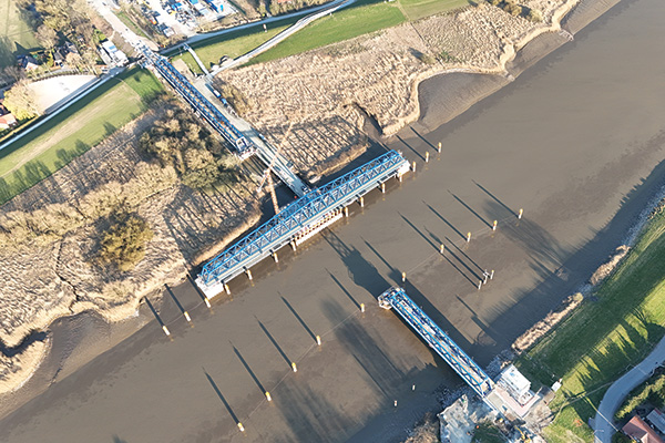
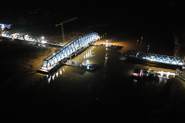
An aerial view of the new Friesen Bridge in open position (MCE - Rudi Marquardt)
The new Friesen Bridge, spanning the River Ems at Weener – about 11km east of the Dutch border – is designed to balance the competing needs of multiple modes of transport at a site long troubled by accidents. Since the first bridge opened in 1876, several replacements have been needed: one after a ship collision in 1922, another destroyed during World War Two, and a later version rendered obsolete in the 1980s due to its narrow width being unable to accommodate ships built at the upstream Meyer Werft shipyard. The most recent bridge was taken out of service in 2015 after a cargo ship strike, resulting in nearly a decade of disruption. Similar to its predecessors, the new bridge must support rail traffic between Leer in Germany and Groningen in the Netherlands, provide footpaths for pedestrians and cyclists, and open to allow river traffic, including large cruise ships passing from the shipyard to open waters. From its inception to near completion, the project demanded meticulous planning, innovative problem-solving, and close collaboration between engineers, contractors and regulatory bodies.
The decision to replace the previous bascule bridge with a swing design was mainly driven by the needs of river traffic. The old bridge required a large crane to physically remove one of its spans whenever a large ship needed to pass – a cumbersome and inefficient process. This limitation became a key factor in designing the new 337m bridge, featuring a 145m-long, 1,800t moveable span.
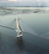
A visualisation of the bridge opening to let a cruise ship pass through highlights how essential the new design is. “The bridge is enormous, but its scale truly comes into perspective when you see it alongside the massive cruise ships it was built to accommodate,” says Lorenz Haspel, director of research and development at sbp and project manager for the Friesen Bridge.
In its normal position, the moveable section functions as a two-span girder, supported at the centre and ends. When raised, however, it behaves like a cantilever, with each end unsupported. This shift subjects the bridge to significant fatigue stress with each opening and closing cycle – more so than the actual passage of trains.
Once complete, the bridge is expected to open about five times a day for smaller and mid-sized sailing vessels. In these cases, the bridge will not need to be lowered and fixed in the open position, but can be partially opened and quickly rotated back into closed position. For occasional cruise ships, or openings for a longer period – the bridge will be fully opened, lowered and fixed on supports at both tips.
The choice of a truss design was driven by both structural efficiency and a desire to honour the Friesland region’s engineering heritage. Preserving the regional design language was a priority for project stakeholders, and the truss form enabled engineers to harmonise the structure with the river landscape. It also offered an effective way to express and manage internal force distribution, especially around the critical central rotating pier.
The concept design was developed by MKP and Schippke+Partner, while sbp, MCC, die-ing and mlIng are responsible for detailed design. Construction is being carried out by the Arge joint venture, comprising Adam Hörnig, MCE, and Depenbrock, on behalf of the federally owned railway infrastructure company DB Infra Go. Construction started in 2022 and work on the superstructure began in July 2024.
Moveable railway bridges of this scale are rare: “We looked at solutions from smaller moveable spans in the Netherlands and adapted those techniques for this much larger bridge. But scaling up those concepts is difficult, it’s not a one-to-one process” notes Gregor Schacht, managing director at MKP and lead for the project’s initial phase. For instance, the rotating mechanism must handle greater deformation, higher loads, and stricter safety requirements – all while maintaining precise operation. This turned the project into a continual process of adapting proven methods to new dimensions, while ensuring full compliance with German engineering standards. “You have to test everything and meet the requirements set by the German authorities – it was all uncharted territory,” adds Schacht.
The new bridge features a sophisticated rotating mechanism: its moveable span is tapered to reflect the distribution of structural forces, with the greatest stress concentrated at the centre – exactly where the bridge is lifted for rotation. The lift-and-rotate system raises the bridge by approximately 1.5m using hydraulic cylinders, after which it pivots 90°.
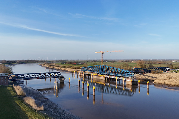
The moveable span is lifted and rotated 90 degrees to accommodate river traffic (MCE - Rudi Marquardt)
A central rotating pier houses six powerful hydraulic cylinders, three on each side, that lift the entire bridge segment. An important design consideration was maintaining a clear regulatory distinction between the bridge structure and the machinery. Deutsche Bahn regulations require bridge components to meet stringent standards, including a 100-year fatigue life and high load capacity. “Machinery, on the other hand, follows the machine code, which allows for lower fatigue resistance and a shorter expected lifespan,” explains Haspel, adding: “Friesen’s machinery was designed with a minimum operational life of 35 years, but will most probably be usable for much longer.”

Render of the rotating mechanism housed in the hub pier (sbp)
The strategic separation not only avoided regulatory complications but also simplifies future maintenance by allowing for critical mechanical elements to be replaceable. “A prime example is the rotating gear which facilitates the swing movement of the bridge,” says Haspel. This component was engineered to be detachable and replaceable, ensuring that critical wear-and-tear parts could be serviced without dismantling the entire system.
Rail connectivity posed another engineering challenge, particularly in managing the thermal expansion and contraction of the long steel rails. To ensure safe and efficient train operation, the bridge incorporates a mechanism that keeps the rails precisely aligned even during opening and closing. The system draws on lessons from earlier projects, such as the Elbe-Lübeck Canal Bridge, but the longer span and greater temperature variation at this site added significant complexity.
To address this, the engineering team developed a solution that shifts the rails laterally inwards before the bridge is lifted, allowing the structural elements to disconnect cleanly and realign accurately upon closure. Two such alignment mechanisms, one at each end of the moveable section, ensure both sides disengage and realign properly.
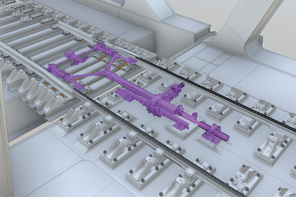
Rail link mechanism (ARGE Friesenbrück)
Once disengaged, the bridge rotates and can either remain in the open position for short-term use or be lowered onto dedicated support piers extending from the rotating pier for longer durations. These secondary piers are essential, as the rotation mechanism is only rated for wind speeds up to force nine on the Beaufort scale. In stronger winds or during extended maintenance, the bridge must be lowered and secured.
The pier arrangement also supports auxiliary systems, including hydraulic control rooms and electrical equipment, all housed within the large central structure. Beneath the bridge, an integrated inspection platform allows technicians to carry out maintenance, repainting, and safety checks without disrupting regular operations. Wind testing was conducted to ensure that critical components could withstand wind loads, safeguarding both operational safety and structural integrity.
The bridge also features ship collision protection – a necessary safety measure after the 2015 accident. While the original design proposed a continuous steel wall for full-length protection, cost considerations led to a revised solution. Instead, the bridge is now protected by steel dolphins that provide targeted impact resistance, significantly reducing potential damage.
A key factor behind the bridge’s operational performance is the interaction between its various physical systems. “First, you have the soil. Then there’s the pier – the concrete structure, which is quite rigid but still has some flexibility. Next is the mechanism, which has its own stiffness. And on top of that, you have the bridge itself, which behaves almost like a spring being lifted,” explains Haspel. “Only when all these components come together do you get the real performance of the structure.”
The engineering team approached these elements as parts of an integrated system, recognising early on that analysing components in isolation would lead to inaccurate assumptions and potential errors. Instead, a multidisciplinary, holistic approach was adopted to factor in soil stiffness, pier flexibility, mechanical tolerances, and structural dynamics as a unified whole.
“This is how the project works – it was always multidisciplinary,” adds Haspel. “We constantly had to involve experts from every field to get answers to even a single question. I think the success of this bridge came from being able to organise and coordinate so many different disciplines.”
Special attention was also given to the bearings supporting the bridge during train traffic. Due to changing Deutsche Bahn regulations, steel-to-steel contact in relatively moving contact surfaces is no longer permitted under high-load conditions. Under heavy loads, particularly with motion, steel-on-steel contact can cause fretting at the contact surfaces due to Hertzian pressure (a localised stress that leads to surface deformation). This issue becomes more pronounced when a rounded element, such as a wheel, presses into a flat surface, for example a section of rail. Relative movement amplifies this problem, resulting in rapid wear from abrasion. To address this, Deutsche Bahn’s new guidelines require the use of sliding materials such as PTFE, MSM or similar compounds for components exposed to continuous rotation or heavy loads, replacing traditional metal contacts. “This was a challenge to achieve because the regulations changed whilst the project was running and we had to overcome the problem on the go,” recalls Haspel.
The project team responded by designing and producing custom bearings that met the new requirements and could reliably perform under the bridge’s demanding conditions. These included two large primary bearings at the rotating pier to carry vertical loads, four more at the bridge tips for additional vertical support, and special alignment bearings to ensure precise positioning.
All the custom bearings help ensure the bridge’s reliable performance even under conditions of thermal expansion and contraction. “When rotating and exposed to sunlight on one side, the bridge behaves like a banana, bending slightly due to heat,” explains Haspel. “And when the span goes down, it needs to be bent back into a straight line – otherwise, you can’t align with the rails.” To achieve this, the centre bearings force the bridge back into the correct axis, operating in two phases: an initial centring using guide wheels, followed by high-precision positioning via spherical surfaces. With an alignment accuracy of less than half a millimetre, the components are critical to ensuring the bridge functions safely and smoothly. Their design underwent extensive review before receiving production approval from Deutsche Bahn.
Transporting the rotating mechanism to site in December 2024 was a challenge in itself. Manufactured in Bremen by Hermann Maschinenbau, the mechanism had to be shipped across the North Sea to reach its destination. However, high winds caused delays, making it too dangerous to proceed until conditions improved. Once the wind subsided, the journey resumed. Upon arrival, the mechanism equipped with hydraulic motors and lifting jacks, weighing approximately 380t, was carefully lifted and lowered into place using a massive floating crane. Temporary alignment supports were used to guide the component into its final position without damaging the already constructed pier. The complexity extended to the mechanisms’ internal systems with engineers coordinating the assembly of hydraulic cylinders, motors and guiding wheels within the mechanism itself on the first and second floor, whilst in parallel the team of Adam Hörnig was still pouring concrete in the upper level of the pier.
The superstructure’s components were manufactured by MCE and pre-assembled at a dedicated site near the harbour, where large tents and facilities were set up to accommodate the scale of the parts. The location was strategically chosen to facilitate transportation to the construction site. The moveable span was fully pre-assembled and balanced before being loaded on SPMTs and floated across the river on pontoons.
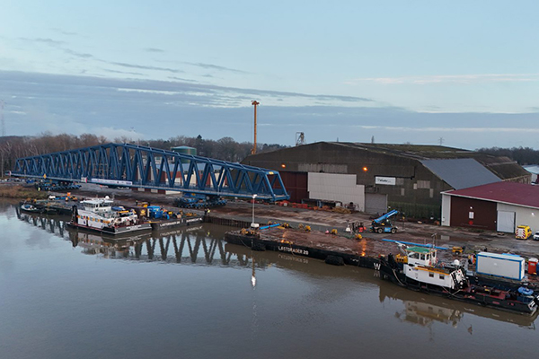
The moveable span was assembled near the site prior to installation (MCE-Rudi Marquardt)
Space constraints were a significant challenge during this phase. The pontoons had to be rotated precisely beneath the bridge span with minimal clearance, leaving little room for error. “There was almost no space; the SPMT wheels were nearly at the edge of the pontoons. It was an exercise in precision by the Felbermayr team,” says Haspel.
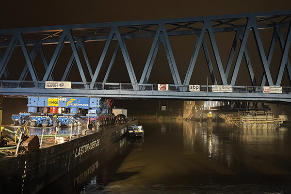
SPMT wheels were nearly at the edge of the pontoons’ decks (sbp-Jonas Greiner)
To facilitate installation, a lock at the river’s connection to the North Sea was temporarily closed. “The lock was closed to keep the high tide water level for a longer period, as the water level otherwise wouldn’t have been high enough for the time needed to manoeuvre the components in position,” explains Haspel.
Welding a structure of this size means that perfect alignment of the centre of gravity cannot be guaranteed. To address this, engineers measured and fine-tuned the rotating span’s centre of gravity during installation using additional weight plates. “This reduced potential deviation to only a few millimetres, achieving a successful outcome,” says Haspel.
Closure of a river lock helped ensure sufficient water level for installation (MCE-Rudi Marquardt)
As of late March, final installations were under way, with bearings being fitted between the rotating mechanism and the bridge deck in preparation for the first test rotation. Construction is expected to conclude by the end of the year.
Client: DB Infra Go
Contractor: Arge JV consisting of Adam Hörnig, MCE and Depenbrock
Concept design: MKP and Schippke+Partner
Detailed design: sbp, MCC, die-ing, mlIng
Other key firms: Hermann Maschinenbau, Felbermayr