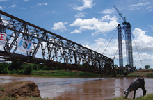
Construction work is progressing steadily on the second phase of the new highway project that is being built across Tokyo Bay. The link is some 4.6km long and connects the central breakwater and the Wakasu area of the bay. The intention is to reduce traffic congestion on coastal roads around Tokyo Port, as well as improving access for container ships, which continue to increase in number.
The Tokyo Bay Bridge forms approximately 2.6km of this section, and is a series of spans being built under the jurisdiction of the Kanto Regional Development Bureau, Ministry of Land, Infrastructure, Transport & Tourism. The main bridge crossing is a steel hybrid structure with truss members and single box girder; it is a total length of 792m and has a main span of 440m and side spans of 160m with a short overhang of the truss at the end of each of the side spans.
Including the chord members, the total width of the bridge is 22m and it has an effective width of 18.5m which is composed of a total road width of 15.5m and footway width of 3m.
The main criteria which resulted in the choice of this structural type relate to the restrictions on airspace given its proximity to Haneda Airport – this is 97m above the Tokyo Bay reference water level, which is known as AP. The area is also subject to shipping restrictions built into the Tokyo Bay East Route ship course. It must offer sufficient width and height to accommodate large ships – a width of 300m, and maximum height 54.6m above AP.
Usually, bridges of this size are designed as suspension or cable-stayed structures with tall main towers, but this was impossible here because of the local conditions, and as a result, a hybrid structure with truss members and a box girder was selected. This bridge is economical and offers a clear shipping envelope. It is also open and scenic.
Bridge High-performance Steel is being used for the superstructure. This product, which was recently developed by Nippon Steel, has higher strength and toughness than conventional steel products. It was developed specifically for bridges, with high weldability and cold working ability, and its use enables various advantages to be gained. Firstly, it is possible to reduce the weight of the structure since the high strength steel means less steel is required.
As a part of its cold bending ability, the bend radius can be up to seven times greater than the plate thickness, resulting in a higher degree of freedom in design and manufacture.
There is no need for preheating before welding and high heat input welding is possible, leading to improved welding procedures and quality.
For the Tokyo Bay Bridge, Bridge High-performance Steel is used for most of the truss members. The steel deck has a thickness of 16mm and the steel products used include SM400A, SM490Y, BHS500 (steel with identical yield points is used) and high-strength bolts S10T, F10T. BHS500 accounts for some 50% - approximately 10,300t - of the total weight of steel which is approximately 20,500t.
Despite recent advances in welding technology, cross joints can still cause defects in welded sections. Therefore, double-level weld joints are being used for this bridge because they offer the greatest assurance against defect development.
All section joints for the main truss that are welded on-site are Z-shaped. In a conventional structure, the welded sections of flanges and webs are in the same positions. However, fatigue considerations dictated that the welded sections of the main truss should be staggered to create Z-shaped joints. In addition, the borders between flanges and webs are not scalloped, which is also intended to avoid fatigue-related problems.
To test the weldability of various types of Z-shaped joints in the yard using the box girder section of full-size truss members, the most severe working environment was recreated in order to verify the validity of welding procedures and to verify conditions in the actual construction. Positive results were observed in nondestructive testing and mechanical testing after trial welding. As for the very difficult welding of lower flanges in a diagonal upward direction, it was confirmed that the work could be performed without problem.
The procedures for assembly of bridge elements on land fall into three main categories: the assembly of bent equipment, the assembly of single members of side span truss, and assembly of side span steel deck blocks using floating cranes.
Bent equipment was set up in a total 32 locations, 16 for each of the main trusses, and rising to a maximum height of more than 37m. The reaction force per location could exceed 500t.
The initial plan was that truss girders would be assembled on land after the bent equipment was built. But limited working space in the yard meant that this was changed so that each panel was constructed in a cyclic operation.
The side span truss member were first transported on a barge to the predetermined unloading area. Depending on the weight of the respective truss members, either the crawler cranes used for ground assembly works or the floating cranes were used to lift the members from the barges.
Steel elements which have been transported by barge are usually washed to remove salt. In this project, however, each member was fully encapsulated during transport to protect it, assure quality and shorten the construction process.
Truss members consist of lower chords, lower supports, vertical members, sway bracing, diagonal members, and middle chords. Each of these was assembled on land using single members. For the on-land assembly, 750t, 500t and 300t crawler cranes were used as the largest member weighed approximately 85t. The total weight of truss members was approximately 3,500t, and the total length was more than 230m.
The steel deck sections are made up of the deck itself, the main girder web plates, main girder lower flanges, diaphragms, and transverse ribs. The sections were divided into eight smaller sections and assembled in the factory - each weighed approximately 410t and was 34m long, 20m wide and 3.5m high. These were assembled at the Shikoku plant, each generally being made up of two smaller blocks.
The steel deck sections were transported on a barge from the factory to the assembly yard and a 1,400t floating crane was used to lift the sections on to the truss girders.
Ground assembly works first started in May 2008 when the first fabricated members started to reach the assembly yards. There were two assembly yards – one at Ariake which was just 4km from the bridge site, and a second at Futtsu which was 34km from the site.
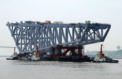
The two large units that had been assembled for the side span were loaded from the assembly yard onto a barge for transportation by three large floating cranes operating in unison. Each unit was 232m long, 24m wide, and 35m high and weighed approximately 7,400t.
A 24,000t class steel barge was used to transport these units on the two installation operations which took place in September last year. The loading procedure was a major operation involving the use of Japan’s largest floating crane, the 4,100t Kaisho and the No 50 Yoshida and the Musashi, both of which have a capacity of 3,700t. This was only the fourth time in Japan, and the first time for 15 years, that three floating cranes have been used in a simultaneous lift.
On board the barge, the truss girder was supported at eight points, which made it imperative to coordinate the three floating cranes in order to