With the sinking of the first caisson taking place in March this year, and the tower foundation scheduled for completion next month (June), work on the new Izmit Bay Bridge in Turkey is moving at a good pace. Construction of the bridge anchorages is also under way and due to finish in late summer, while fabrication of the tower and deck units is being carried out simultaneously at a local fabrication shop.
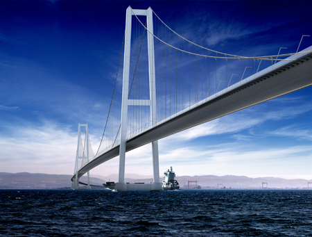
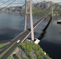
The construction of a 1,550m-long main span suspension bridge in little over three years – a very short period for such a large bridge – and in a marine environment, is creating many challenges for the contractor. The structure is a central part of the new 420km-long Orhangazi-Izmir motorway, and is being built to carry this new link across the Sea of Marmara at the Bay of Izmit in northern Turkey.
The motorway is being promoted by Otoyol Yatirim Ve Isletme, a joint venture of Nurol, Ozaltin, Makyol, Astaldi and Gocay which is contracted by Turkey’s General Directorate of Highways as build-operate-transfer concessionnaire for a period of 22 years and four months from September 2010. Nomayg Joint Venture, which consists of the same six companies, is the engineering procurement construction contractor responsible for building the whole 420km-long road, which includes the Izmit Bay Suspension Bridge.
After a 2010 call for tenders, construction of the bridge was contracted in July 2011 to a consortium of IHI Infrastructure System and Itochu as EPC contractor. In September 2011 the contractor was given notice to proceed with the detailed design of the bridge, and this was carried out by Cowi under supervision by IHI. The bridge is situated in a very active seismic area where in 1999 the 7.6 Kocaeli earthquake occurred on the North Anatolian fault in 1999.
Set for completion in 2016, the new bridge will become the world’s fourth longest suspension bridge. Nomayg’s engineer Aecom-URS set certain criteria for the reference design, in that it should be a suspension bridge, with a total length of between 2.8km and 3km, and a main span of between 1,550m and 1,700m. Other criteria for the size of navigation channel and locations of the main tower foundations were also set. The chosen design has a main span of 1,550m and side spans each 625m long.
The total suspended deck is 2.8km and it is continuous between the two side-span piers. The main cables deviate at the side-span piers toward the cable anchorages which are below the deck of the transition spans. The anchor span of the main cable between the side span pier and the splay saddle is each 95m and there are 120m and 142m-long transition spans on the north and the south.
Ground investigations carried out by Fugro led to some important design changes; a potential secondary fault was discovered far below the ground level at the planned location of the south anchorage. As a result, the south anchorage was moved by 138m into a safe zone between faults, and the south side span pier and tower foundations were also moved by smaller amounts.
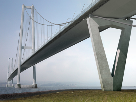
What had been intended to be separate concrete slabs at the front and rear of the south anchorage were integrated into a single large slab, on which the side span pier and the front and splay leg of the anchorage were located. This will allow them to move together in the event of a strong earthquake. The tower foundations are concrete caissons on a gravel bed at 40m below sea level for the north and south foundations.
Cast in situ concrete within west steel shaft
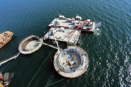
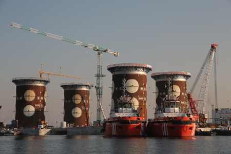
The soil below the caissons has been improved by the installation of steel pile inclusions to about 35m below the sea bed; this is intended to provide the required bearing capacity and eliminate any potential risk of liquefaction during earthquakes. The two caissons were partially constructed in a dry dock with the base slab and outer walls fully cast in several stages, and the inner walls being partially built. They were then towed to the wet dock, where the inner walls were completed, the top slab cast and the steel shafts installed, the lower part also having its concrete cast. Since 100 years of design life is demanded, very high concrete quality is needed, with a low chloride migration ratio, low permeability and low heat of hydration.
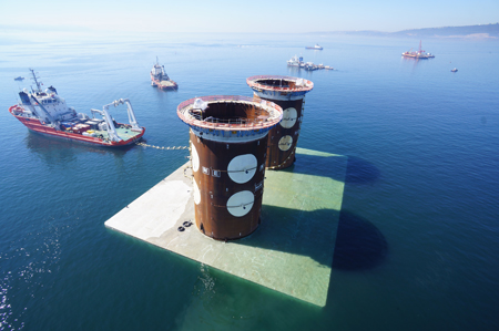
North tower foundation final launching and immersion
At the same time as caisson construction was proceeding, dredging was carried out at the foundation sites using a grab dredger over an area of 87m by 74m and up to 5m depth. Some 195 inclusion piles of 2m diameter and up to 35m long were installed by an underwater hydraulic hammer or hydraulic hammer on a barge using follower pile. The gravel bedding was placed using a tremie pipe mounted on a floating barge crane, and the surface of the gravel was levelled using hydro-mechanical levelling equipment.
North tower foundation final launching and immersion
Four tugs were used to tow the caisson to a position close to the installation site and these tugs then connected themselves to a pre-laid mooring. The caisson was kept in position by means of the tug’s winches, adjusting the wires to get the caisson into position as its position was monitored by GPS. Water was used as ballast in order to submerge the caisson and steel shaft, with the specially-designed chambers allowing tight control of the procedure. Once in place, all the chambers are filled up with water for stability. Anti-scour rock protection is then placed around each caisson, and the plinth and tie-beam construction, which is the final stage of the tower foundation, is carried out.
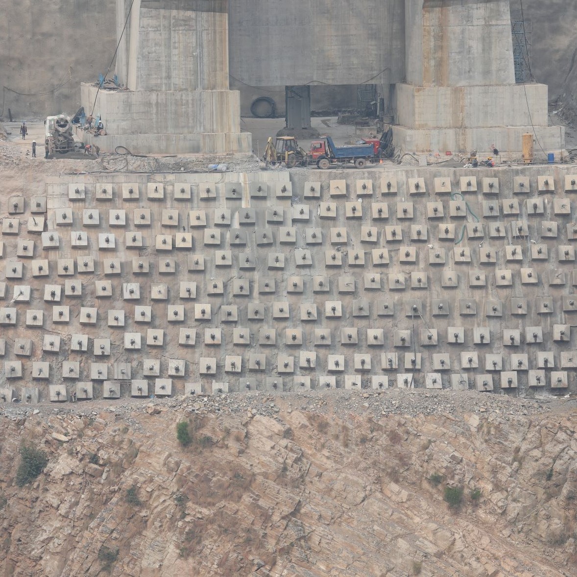
The south cable anchorage is built on reclaimed land, on a large concrete slab which it shares with the side span pier and the transition pier. The intention of this is to reduce the risk of relative movement between the cable anchorage and the deviation saddle on the side span pier, which would introduce a huge force in the main cable under a strong earthquake. Construction of the south anchorage began with construction of the diaphragm retaining wall below ground which is 59m wide and 125m long.
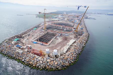
South anchorage aerial photo
In plan it is a rectangular shape combined with two overlapping circles, the intention being that the 1m-thick retaining wall is supported to a great extent by the circular shapes, minimising the number of struts required. The double circle at the rear has a diameter of 59m while the rectangular part at the front is 19m wide and 37.6m long.
After excavation inside the retaining wall, the large concrete slab was built block by block to suit a concrete supply of 1,000m3 per day and maintain the temperature rise due to heat of hydration below the permitted value. The cable anchorage construction is scheduled to begin in parallel with concreting of the final layer of the slab and is completed with placing of the roof which will be built once the main cable is erected.
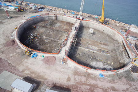
South anchorage aerial photo
The north anchorage is constructed on land and in contrast to the south anchorage, is founded on relatively good quality rocks. Hence the front and rear legs of the triangular cable anchorage are built on separate concrete slabs connected by tie-beams, reducing the amount of concrete required. However the construction procedure is almost the same; block by block construction vertically and horizontally to suit the concrete supply capacity and limit the rise of temperature in concrete below the permitted value.
Both the main towers and the deck of the new bridge are being built in steel. The 235m-tall towers have two legs and two cross-beams; the legs are 7m by 8m cross-section at the base, reducing to 7m by 7m in the top, formed of four stiffened panels throughout. Each tower leg is divided into 22 blocks to suit a lifting capacity of crane used for the erection and the tower leg blocks are connected by welding for perimeter plates and by slip resistant connection for vertical stiffeners.
Mass dampers are provided to mitigate vortex-induced vibration during construction and in-service condition. The eleven lowest segments of the legs are each formed by welding four stiffened panels together at the fabrication shop; for the upper segments the four panels are connected by friction resistance bolts at the site.
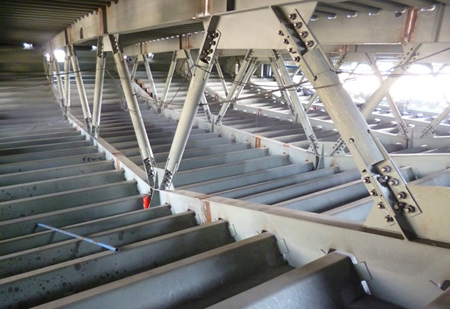
Fabrication work under way
All fabrication and trial assembly is being carried out by local steel fabricator Cimtas, under the supervision of IHI. After the trial assembly, the tower leg segments will be dismantled into separate segments, and further to four panels where applicable, in order to be shipped to the site. The lower tower leg segments and the lower cross-beam will all be erected using a floating crane, while the tower legs segments 12 to 22 and the upper cross-beam will be erected by a self-climbing crane mounted on the support structure connected to the lower cross-beam.
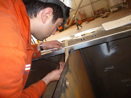
Inspection of steelwork
Once the towers are built, the two main cables will be installed – on the main span these are formed of 110 pre-fabricated parallel wire strands each consisting of 127, 5.91mm-diameter cable wires with a breaking strength of 1,760Mpa. The main cable on the side spans will have two extra strands of the same size. The cables are designed to be supported on saddles at top of the tower, at the side span pier and at the anchorages, and connected to the anchor blocks. Corrosion protection will be provided by S-shaped wrapping wire, paint and a dehumidification system. Hanger ropes will be parallel wire strand, typically formed of 133, 7mm-diameter wire with a breaking strength of 1,760MPa, connected to a cable clamp at the top and hanger anchorage at the bottom.
Due to a large longitudinal relative movement between the main cable and the suspended deck and a large transverse movement and tilting of the suspended deck under traffic and strong seismic activity, many hanger ropes are equipped with cylindrical bearings at the cable clamps and spherical bearings at the deck anchorage. In order to carry out the erection of the main cable, an aerial walkway equipped with hauling system will be installed, and the cables saddles will be set back before the PPWS main cable strand is drawn out. Normally a pilot rope would be drawn across the sea between the two towers, and this would be used to haul the catwalk strands; in this case the shipping channel will be closed for a short time however for this bridge the catwalk strands themselves will be pulled across the sea in order to shorten the construction time.
The PPWS will be pulled out from reels installed behind the north anchorage and hauled to the south anchorage by the hauling system as placed on the guide rollers provided on the catwalk. As soon as the strand arrives the south anchorage, it is clamped by the tensioning system at each cable saddle, tensioned and then lifted off the guide rollers and shifted laterally into the cable saddles.
Those strands pulled during daytime hours will be connected to the cross head slab at the anchorage and then adjusted to the correct design length by sag control during the following night. Upon completion of the erection of the PPWS, they will be compacted into a circular shape with the specified void ration, firstly with a simple tool to enable the purpose-made compacting machine to be installed so that it can complete the process.
Erection of the cable clamps and the hanger ropes will then be carried out simultaneously by using a bogie running on the main cable. Construction of the cable catwalk is programmed to start later this year, with cable erection taking place in 2015.
Next year will also see erection of the deck units for the new bridge. The suspended deck is a single, orthotropic box girder which is 30m wide and 4.75m deep and has a 2.8m-wide inspection walkway attached to each edge. Its suspended length is 2,682m long, being continuous between the two side-span piers; it is supported transversely both at the tower location and at the deck ends and vertically only at the deck ends.This deck will be erected in 111 segments to suit the fabrication, transportation and erection capabilities available.
Stiffened panels are currently being fabricated at Cimtas workshop in Turkey, and they will subsequently be assembled into deck segments for erection at the assembly yard of the company’s shipyard at Golcuk. Each completed deck segment will be matched to its adjacent unit as part of the trial assembly, a procedure which is likely to be a running trial assembly with a minimum of three segments at a time being assembled to be adjusted for alignment and camber.
After trial assembly, the deck segments will be dismantled and stored at the yard, ready for the three-hour journey to the site for delivery in the correct erection sequence. Segments will be loaded onto barges and fastened to prevent any damage during the transportation. Erection is intended to be carried out in two different ways; unsuspended deck segments at the tower and at the deck ends will be erected by use of a floating crane which has a 1,600t lifting capacity.
Meanwhile the suspended deck segments will be installed using a special device with a 350t lifting capacity. A self-propelled barge capable of dynamic positioning will be used for transportation in order to minimise interruption to the marine traffic. Each suspended deck segment will be connected to the end of the previously erected deck segments before the deck weight is released from the floating crane or the lifting device. Two different types of connections will be used; the matching pieces prepared for top and bottom plates to re-establish the deck alignment from the trial assembly, and temporary connections on the nose plate to take vertical shear force and on the top plate to resist wind forces.
Yasutsugu Yamasaki is deputy project manager, Naoki Ikoma is general manager for substructure construction and Mitsuhiro Kudo is general manager for superstructure construction for the Izmit Bay Crossing for IHI Infrastructure System Company. Ali Nebil Ozturk is employer’s representative and Fatih Zeybek is project manager for Nomayg.