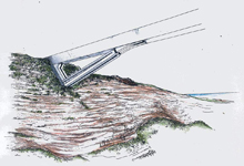
The bridge was designed by architect Zaha Hadid and structural engineer HPR, and its construction by contractor Archirodon Construction (Overseas) began in late 2003. The bridge was opened to traffic at the end of last year.
The bridge has twin cast in situ concrete decks which are almost 24m wide and 800m long, and are divided into 11 spans ranging from 60m to 150m long. Three pairs of steel arches are included as part of the statical support system.
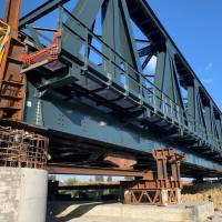
Two marina arches are each created of three segments which range from 430t to 640t, making a total 3,300t. Two main arches are each formed of six segments ranging from 300t to 630t, making a total of 6,000t, and there are two secondary arches formed of two segments each, 440t and 550t making a total of 2,000t.
The final design required the arch segments to be welded by full pen weld of the boxes, which consist of plates 50mm to 100mm thick. To perform these welds the segments had to be supported and held together very securely for periods of time ranging from three to eight days for the biggest welds. A custom-made lifting system was chosen against crane lift, because of the risks of availability and the access/manoeuvring that a huge floating crane required.
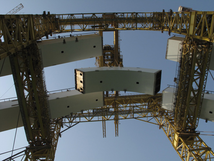
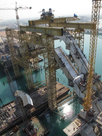
This lifting system consisted of four or six four-legged towers on steel tubular piles, horizontal transverse support trusses with appropriate stubs with lockable hydraulic jacks for support of the segments, two longitudinal box main beams for support of the lifting crane, two transverse box crane beams moving longitudinally and a square steel frame turntable moving transversally and bearing the four lifting strand-jacks and allowing 360º rotation of the lifting system and tilting of the segments in the vertical plane.
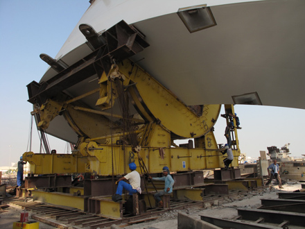
A special machine dubbed the rotator was used to turn the segments from the fabrication position, outer web downwards, to the required position ready for lifting, with bottom flange down.
The tower consisted of four HEB columns on a 5m square with appropriate bracing, tower spacing at 40m by 32m, stabilised longitudinally by horizontal steel trusses and transversally by pairs of 19-strand inclined tendons. Founded on 914mm-diameter, 16mm-thick tubular piles up to 25m long, heavily braced within each group and between the groups, the whole system was properly anchored to absorb/counter the design horizontal forces.
The transverse support trusses were heavy truss units with chords at 5m by 3m centres, spanning 32m at appropriate elevations. The main beams were box beams of dimensions 1.9m by 4.1m by 55m, spanning 40m and cantilevering approximately 15m on top of the towers.
Crane beams were also boxes with dimensions 1.25m by 3.5m by 33m, spanning 32m. Each was equipped with a 16m-long launching nose for positioning and removal. They were positioned on sledges and slid longitudinally over the main beams.
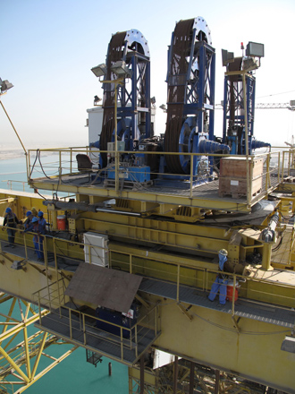
The turntable was formed of two superimposed square frames, the lower one almost 6m square, sliding transversally over the crane beams; the upper one 5.9m by 2.4m, rotating on PTFE pads on a circular stainless steel track of the lower one, with the help of four double-acting hydraulic cylinders.
The lifting gear consisted of four, 330t capacity multi-strand strand-jacks at 2.4m by 3.6m centres. The heaviest segment and lifting gear together added up to 740t, which was the maximum weight. However the process of tilting the segments during lifting, starting from a horizontal position and ending at an angle of up to 45º, meant that the load in the strand-jacks varied from 40t to 600t per pair. The jacks were provided and operated by VSL Heavy Lifting.
In order to hold the segments in place and perform the weld properly while minimising the risk of cracking, each segment was supported on one front end support on a transverse support truss, and clamped to the previous one.
Additionally this clamping had to hold the joints tightly, preventing any movement during welding. This was achieved by inserting adequate shear plates which could resist shear up to 6,000kN and stressing the segments against each other with up to 120, 32mm-diameter Macalloy bars to withstand moments up to 150,000kNm.
The rotator consisted of two circular discs of 7.5m diameter, missing approximately one quarter, strongly braced together and rotating on stainless steel strips on PTFE pads. The motion was provided by two double-acting 200t hydraulic jacks.
The concept and preliminary engineering was finalised by the in-house engineering department. Final design and arch erection construction engineering was done by VSL’s technical centre in Singapore while checking and general construction engineering was carried out by Buckland &Taylor. The in-house engineering team also designed and detailed the rotator and a lot of secondary or ancillary gear such as the lifting tackle. The methodology and kinematics which was of extraordinary complexity covering the whole process from arch fabrication, load-out of the elements to the vessel, transfer to barges, rotation, lifting, clamping and welding was carried out by Archirodon’s in-house engineering department. Some 40% of the steel fabrication for the temporary works - out of a total of 2,000t - was done in-house and the remainder by Fabtech in Jebel-Ali.
The segments were fabricated and transported to the site supported on the outer web, to fulfill the matching requirement. They were placed on the rotator and rotated to the proper position, leaning slightly outwards, but longitudinally horizontal. They were attached to the lifting gear and lifted, rotated, tilted and shifted to the final position, matching the previous elements and seated on a transverse support truss near the other end.
This operation was very delicate, requiring several transverse and longitudinal movements – the former made by the turntable, the latter by the cranebeams – as well as tilting.
While held by the jacks, they were clamped and lowered on to the supports before being released and welded. All segment supports were equipped with load cells. The forces expected during lifting and support reactions throughout the erection were calculated beforehand and then constantly monitored to verify the structural behaviour of the whole system, both the arches and the temporary support structure.
Due to time constraints, the marina arches were erected using a 1,500t crawler crane operating on a specially-built floor within the cofferdam.
The nature of the project, which has no geometric symmetry or repetition, meant that each of the total 22 elements required a separate detailed study and work procedure starting with the rotation, through the lifting, the final positioning, clamping and welding. The development of the methodology went hand-in-hand with the engineering and design of the lifting structure and the site implementation. Erection of the arches was carried out successfully and can be considered one of the most challenging heavy erection operations undertaken in the bridge industry in recent years.
Costas Constantoulakis is project director and Roy Lengweiler is project manager of Archirodon Construction (Overseas)