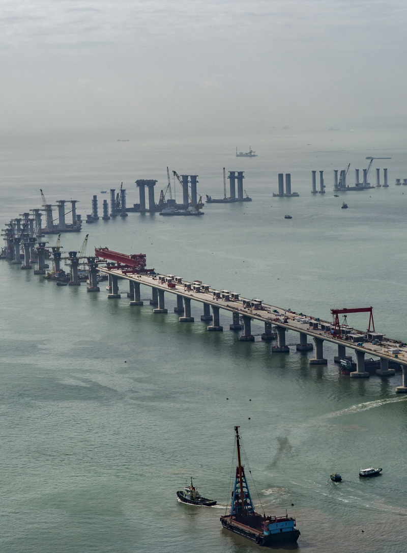
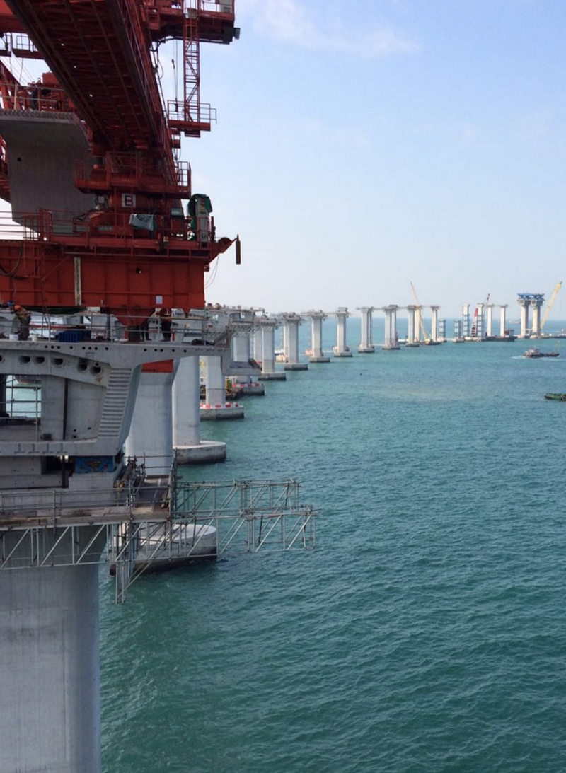
With construction of foundations and pier caps complete, and the vast majority of the bridge piers now built, work to erect the deck of the 9.4km of viaducts for the Hong Kong Link Road will step up to full speed in the coming months. The twin viaducts, which will carry traffic to the Hong Kong – Zhuhai – Macao Bridge, are major projects in their own right and feature what is believed to be the world’s longest precast segmental spans.
The HKZM Bridge will be one of the world’s longest sea-crossing highway links, creating a fixed connection between the two sides of the Pearl River Delta, and connecting Hong Kong to Macao and Zhuhai. As an essential transport construction project, it forms part of China’s national high-speed road network plan.
The viaducts of the link road will form the connection from the main bridge at the Hong Kong SAR boundary to Scenic Hill on Chek Lap Kok Island, where Hong Kong’s international airport is situated. The project covers design and construction of approximately 9.4km of viaducts supporting dual three-lane carriageways, and the US$1.67 billion contract was awarded to Dragages-China Harbour-VSL joint venture in May 2012 by the client Hong Kong Highways Department, with supervision by its representative Arup. Completion is due at the end of 2017.
YWL Engineering was appointed as the designer and construction engineering consultant for the marine viaducts, Mott MacDonald for the design of the land viaducts and Bouygues Travaux Publics as the designer for the long-span viaducts.
In the early stages of the project, various structural schemes were investigated to satisfy the site constraints and functional requirements of the project. To create a span of 180m, a cable-stayed bridge solution was also studied but subsequently rejected due to the proximity of the airport. Another solution with composite steel and concrete deck was also studied, based on the use of a wide steel box. However, this concept was not commercially viable and it did not meet the sustainability criteria as it would require significant long-term maintenance. Therefore a precast concrete segmental option was selected, and this choice posed a major technical challenge. Building a precast segmental span of 180m will be a world record.
The project incorporates a total of 115 spans which can be split into four different bridge types from west to east; the western viaducts, which include three 150m-long navigation spans; a central turnaround facility which extends across 22 spans; the airport channel viaducts, which are long-span structures with spans ranging from 100m to 180m, and the land viaducts, where spans vary to suit the ground conditions.
The western viaducts have regular spans with a typical length of 75m, and there are three spans of 150m which allow one-way navigation. A grade-separated turnaround facility is proposed at the central point, with slip roads in the form of single-lane viaducts diverging from the HKLR mainline carriageways on both sides and forming an elevated junction in the middle of the viaducts.
For the articulation, a typical viaduct unit of eight-span continuous deck – 600m long – was adopted with optimal use of bearings and movement joints so as to reduce future maintenance effort. Other than the first and last viaduct piers, all others are monolithic with the bridge deck. To improve the aesthetics, the length of the end span was made the same as the internal ones in order to create a regular visual ‘rhythm’.
The viaducts on the airport channel follow a double S-curve in the channel and merge with the viaducts on land. About 2km of the land viaducts are on the southern side of the airport island and these have variable span lengths to suit the ground conditions.
The viaduct structures are designed in accordance with the HKSAR Government Highways Department’s Structures design manual for highways & railways and the employer’s requirements as part of the contract documents. In general, the viaducts are designed for ultimate limit state and serviceability limit state according to BS5400, with a design life of 120 years, except in the case of two special load scenarios; seismic loads and ship impact. These are considered as extreme events and designed under structural integrity limit state.
Eurocode 8 – Design of structures for earthquake resistance was used in the seismic design, but the two seismic performances in EN are extended to three performance requirements; no damage, repairable damage and no collapse with three corresponding levels of seismic design actions.
In the design for ship impact, reference was made to IABSE’s Ship collision with bridges and AASHTO’s Guide specifications & commentary for vessel collision design of highway bridges.
The western viaducts cross open water to connect to the main HKZHM Bridge. The seabed in this area is generally underlain by 30m-40m of soft marine clay and due to the presence of fault zones, the bedrock in some locations is more than 100m deep. As it approaches the airport island, the geology becomes drastically different and the bedrock is closer to the surface. Since there is an archaeological site in the vicinity, no permanent or temporary structures are allowed to be built in this sensitive zone and therefore, decks spans of up to 180m long are necessary. Long-span decks are also continuously employed in the airport channel where a two-way navigation channel of 46m width must be provided.
Within the airport channel, all pile caps are kept below the level of the seabed in order to minimise their hydrodynamic impact. However this does not apply to pile caps on the navigation span which extend above the seabed to +3.95mPD.
The viaducts on land are mainly located on the sloping seawall, near the tunnel portal at Scenic Hill. As well as the difficulties of working in a marine environment, other critical site constraints for viaduct construction are the potential impact on Chinese white dolphins; the logistics for concrete supply; construction noise, and the height restriction which must be observed due to the proximity of Hong Kong Airport.
A total of 725 bored piles is used in the project; 65 for the land viaducts and 660 for the marine viaducts. Those on the land have a diameter of 2.8m while the marine viaduct piles have diameters of 2.3m, 2.5m and 2.8m. The significant variation in geology is reflected in the pile lengths, which vary from 7m to 107m. Generally they are designed as end-bearing piles with an allowable end-bearing capacity of 5,000kN/m2 or 7,500kN/m2 depending on the quality of the rock. The friction resistance in the completely decomposed granite and alluvium was generally ignored.
The long piles are located mainly in the marine viaducts in the western waters where the geology is characterised by a thick layer, up to 40m, of weak marine deposits immediately below seabed. It is underlain by alluvial clay/sand, and completely decomposed granite. In some locations, bedrock is more than 100m below sea level. Friction bored piles are employed for such locations, given the limitations of the piling machine. These piles are both shaft and toe-grouted and are arranged in groups of three to six, with diameters of 2.3m, 2.5m or 2.8m.
It was considered important to provide a safe and dry environment within which construction could be carried out in the marine tidal zone. To achieve this, sacrificial concrete shell formwork was developed, integrated with the permanent cap to offer additional protection against the corrosive marine environment.
There are seven different types of generic concrete shells including those for the dolphin structures; in a typical shell the wall thickness is 300mm and the bottom slab is 450mm. Two aspects of the shell design were considered, namely, strength requirement and durability performance. In strength design, the shell has to resist the concrete pressure from the permanent core, buoyancy forces and wave loads, construction loads and thermal effects due to expansion of the core from heat of hydration. Although the shell is not part of the permanent structure in terms of resisting the service loads, it still has to protect the pile cap against the corrosive marine environment during its design life of 120 years in the durability assessment.
Due to the complex shell geometry, three-dimensional finite element analyses were conducted to simulate the structural behaviour of the system in different stages. It was found that the thermal stresses induced by concrete hydration in the permanent cap would be the governing load scenario and tensile stresses could be as much as 7MPa. If no effort was made to reduce the early thermal effects, for example by using cooling pipes, a significant amount of the tensile reinforcement would be needed to avoid cracks on the surface.
Driven by the need to release the thermal strain induced in the shell, a novel idea was conceived in the design; a thin layer of isolating material with specific mechanical and thermal properties was mounted on all inner faces of the shell.
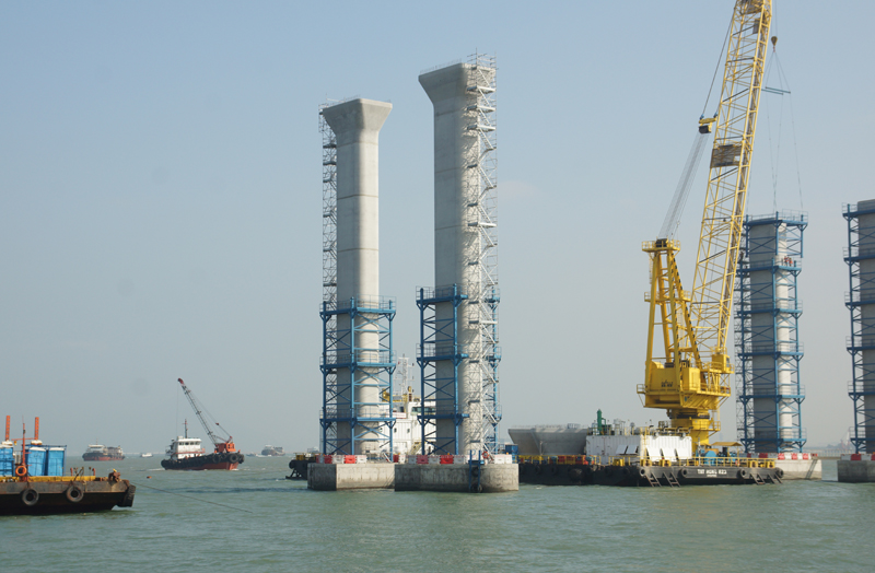
In the western waters, all the tall piers except the twin-blade piers for the long-span decks were designed as precast prestressed concrete structures. The typical pier cross-section is hollow with external dimensions of 5m by 3.2m and internal dimensions of 3m by 1.5m. A typical precast column unit is 6m high and an in situ stitch of 400mm is used to connect the pier base with the first precast unit. U-shaped internally prestressed tendons are used to connect the precast units. Some tendons are embedded into the pile cap while others are in the base due to space limitations and ductility requirements at the column base. The tendons are anchored at the pier head instead of the pier segment to keep these two construction activities separate. The prestressed piers are designed as class 1 structures under the service load combinations as stipulated in the Structural design manual for highways & railways.
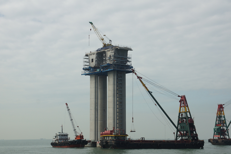
The monolithic connection between the pier segment and the pier was achieved using prestressing instead of reinforcing bars, and all structural components were precast. This is a new technique in Hong Kong and is driven by the need to minimise in situ concrete work in the marine environment and to optimise the erection cycle time. After the pier segment was installed and its geometry adjusted, its spatial position was fixed on temporary supports. The precast plinths were then grouted prior to application of the vertical nailing prestressing in the formation of the monolithic joint. The U-shape nailing tendons used in this project were designed to be anchored on top of the pier segment to make the stressing operation easier.
A mixed prestressing scheme with both internal and external tendons is used in order to minimise the weight of the deck and reduce the erection cycle time. Internal cantilever tendons are provided to support the self-weight of the cantilever decks while external continuity tendons and internal span tendons are used to resist the other loads.
All the external tendons are designed to be replaceable, with spare ducts provided for the replacement operation. In order to enhance the performance and constructability of these deflectors at deviator segments, a double curvature diabolo surface was adopted in the design instead of the conventional single curvature steel tubes that are commonly used in Hong Kong.
Long-span viaducts are used for the navigation channels in the western waters and the viaducts near the headland and airport channel. The navigation channels in the western waters are crossed by a five-span bridge unit which has three adjacent 150m-long spans with 109m-long side spans. Movement joints and bearings are only provided at the ends of this 668m-long bridge; elsewhere, the twin-blade piers are monolithically connected to the deck. This form was selected with the intention of minimising the longitudinal stiffness of the bridge and reducing the locked-in effects caused by creep, shrinkage and thermal deformations.
On the headland, the viaduct has been designed as a three-span continuous structure with a 180m-long clear span in the centre and 115m-long end spans to cross an archaeological site in the island. Meanwhile at the airport channel, four bridge units with two generic four-span configurations were proposed. The configurations are two 165m-long centre spans with 109m-long side spans and two 180m-long centre spans, with 115m-long side spans.
The 180m-long spans are at the upper limit of the precast segmental concrete bridges that have been built so far. With a box depth ranging from 4m to 10m, the span to depth ratio is 1/45 at mid-span and 1/18 at the pier-top segment. The monolithic internal twin-blade piers provide strong fixity for the long-span decks, while bearings at the ends allow the release of large movements caused by creep, shrinkage and thermal effects.
This monolithic deck-pier connection enables the demands on the temporary stabilising system for cantilever erection to be minimised, but it also results in strong interactions between the decks, piers and foundations. Longitudinal behaviour in particular is very sensitive to foundation stiffness, especially for bridges which have short piers such as those on the headland and over the airport channel. The longitudinal portal frame behaviour will create high tension forces in the piles in the event of seismic loading or longitudinal movement effects. To reduce these effects, some of the bridge cantilever were jacked against each other before the stitch was cast.
In this project, the decks of the two carriageways are generally separate, with a typical box width of almost 17m. However due to the requirement for sight distances on structures with a tight curvature radius of 513m, some of the structures have been widened to almost 18.5m. In these areas, the two decks are connected transversely by a cross-beam at the pier-top segment. This structural arrangement has resulted in interaction between the two decks and the complicated portal behaviour in both the longitudinal and transverse direction.
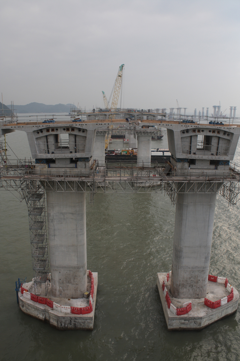
The pier-top segment is one of the most complex structural elements in the deck design. It serves two main functions: to transfer the longitudinal loads from the span to the blade piers and to connect the adjacent decks via the cross-beam. The segment is formed of three, 3m-long elements which are formed using precast shells which are subsequently filled with cast concrete together with the cross-beam. Shear keys are provided at the connection between the precast and cast in situ concrete and transverse prestressing is used to mitigate the effects of differential shrinkage and to enhance the beam’s shear capacity.
The land section of the viaduct has span lengths ranging from 35m to 65m. The deck is supported by cast in situ portals, with each column being supported on a single pile.
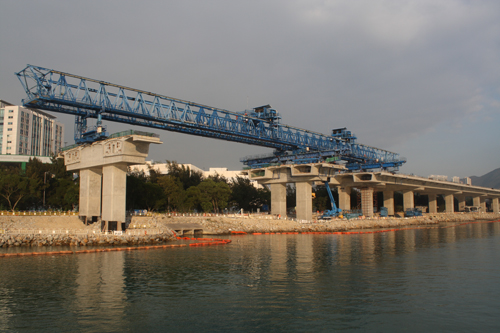
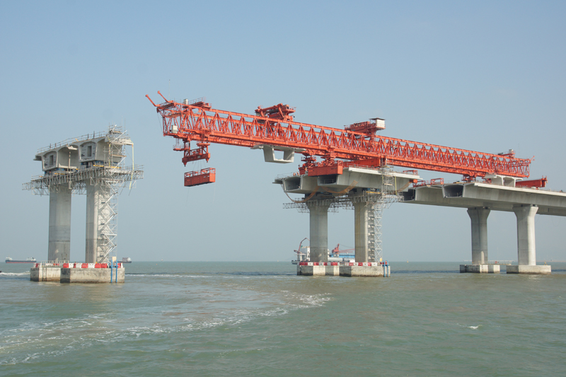
The five bridge units along the sea wall are twin decks, and the sixth has three decks integrated into the portal structure. The viaducts are designed as precast segmental structures erected by the balanced cantilever method using an overhead launching gantry. To enable appropriate structural behaviour, the side spans are on sliding bearings and intermediate ones are fully embedded into the portals.
The key to the success of a segmental bridge project is good standardisation so that works can be executed in a controlled and repetitive manner. In this project, the segment geometry was carefully designed so that variation in construction method and equipment such as segment formwork could be minimised. For the typical 75m-long spans, a constant 4m-deep box was used. For the long span decks of 150m to 180m, the segment depth varied from 10m at the pier to 4m at mid-span. The segment design in the shorter spans was re-used in the long ones; for example, segments designed for the typical 165m span would be replicated in the 180m long deck; the extra 15m deck length was then made up with additional segment types.
An off-site segment casting yard which was set up in Zhongshan in mainland China to cast the 5,694 precast deck segments has six operation lines. It covers an area of about 20ha and is equipped with all facilities such as concrete batching plant and lifting gantries for casting and handling of the segments.
Three of the operation lines and 33 sets of formwork moulds are dedicated to day-to-day segment production, while the remaining lines are reserved for storage space. About 1,000 segments can be stored in the yard to cope with the actual deck erection cycle on the site. Two loading jetties were set up with heavy-duty cranes to enable segments to be loaded directly onto barges of different capacities depending on the type of the segments. A liaison and logistics control team manages the deployment of barges for delivery, taking account of all factors such as the travelling distance – approximately 43km – the number of segments per barge, weather conditions and deck erection cycle time on site.
After each segment is cast, a three-dimensional digital model is updated and the next mould is adjusted to bring the geometry of the subsequent segment as close as possible to the required alignment. Statistical analysis is carried out to confirm the as-cast shape.
On site, the first segment is adjusted in relation to the as-cast geometry in order to minimise any potential misalignment at the mid-span stitch. This can be identified at a very early stage by analysing the erection follow-up tables.
A similar approach is adopted for both precast columns and decks. At the casting yard, the shape between the column segment to be cast and the adjoining one is recorded, and the final geometry calculated superimposing the achieved geometry between the two segments.
The use of the prestressed method in the formation of monolithic deck-column connection and pier works is a new attempt in this project driven by the need to minimise the in situ concrete work and to optimise the erection cycle time. Special design and construction considerations for the use of precast concrete shells in the marine pile caps and pier segments of the long-span viaducts are also novel ideas motivated by the construction requirements. Geometric characteristics in the design and on-site geometry control/erection follow up involve challenging technique adopted in this project particularly for the long-span viaducts which have maxiumum spans of 180m built using the balanced cantilever erection method.
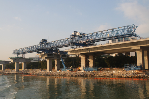
On site, the contractor is currently using two launching gantries and four sets of lifting frames and two hanger beams on a total of 12 work fronts to erect deck segments on the western bridge, the turnaround and the land viaducts. Another two sets of lifting frames are due to come into operation this month (February). By the end of last year, one of the launching gantries had erected more than half of the 1,020 units it is scheduled to erect, and the other just over a quarter of its scheduled 1,756. Both are working two shifts daily.
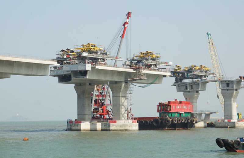
Between them, the six sets of lifting frames are scheduled to erect a total of 1,940 segments, and the hanger beams will erect 356 in total. The contractor’s fleet also includes more than 40 vessels, three of which are large barge cranes, each of which has a capacity of 250t. A fourth large barge crane is being brought into service this month.
Man Chan, Dominique Droniou and Wai Kwong Poon work for the Dragages-China Harbour-VSL joint venture.