The design of a movable bridge adds complexity to the usual bridge design process. Several additional engineering disciplines participate, including mechanical, electrical and potentially also hydraulic, and these must be coordinated with the structural and civil aspects of the design. Additionally, movable bridges are often regarded as statement projects with high client expectations and architectural ambitions.

The success of a movable bridge project is judged by the same criteria as a static bridge, but with the added requirement of reliability. If the bridge looks amazing but rarely operates as intended, it will be regarded as a failure. The key to reliability is keeping the operating equipment simple and ensuring that any equipment that is provided can be maintained. Simplicity is achieved by avoiding reliance on complex electrical systems or intricate mechanical assemblies.
Electrical sensors are often at the root of reliability issues and hence sensing equipment should be sufficient to ensure safe operation through redundancy or via higher reliability component selection, but excessive sensing should be avoided. The key task is to optimise the sensing arrangement so that it is no more complex than it needs to be. Sensors should be positioned so that they are out of the reach of the public to reduce the risk of vandalism, but should also be accessible to enable them to be maintained and adjusted. It is often the case that these two requirements are at odds with each other and the most appropriate solution is site specific.
One option is to locate sensing equipment behind covers and hatches that can be accessed by maintenance personnel but are not obvious or visible to the general public. Complexity in mechanical assemblies most likely results in a greater number of pins, pivots and linkages. These will all need maintaining and may wear over time, resulting in deteriorating performance of the bridge. As noted, the second driver for reliability is a system that is easy to maintain, and this is achieved by ensuring that any equipment that may need maintenance, including maintenance-free bearings, can be accessed easily and effectively.
Access for maintenance is much improved if its design is considered right from the start. Ensuring ample space around equipment such as hydraulic power packs also eases the maintenance activity. The importance of ensuring that maintenance activities can be carried out easily should not be underestimated; the more difficult the maintenance activity, the less likely it is to be carried out. Access for inspection and replacement of electrical wiring and hydraulic pipes and hoses may also need to be considered in the structural and civil design.

The two aims of simplicity and maintainability are core aims for the design of successful movable bridge projects. At the start of a project, the various parties need information from one another in order to start the design process. The mechanical designer needs to know the mass and inertia of deck units in order to size driving mechanisms and power requirements, whilst civil and structural designers need to be aware of the loads that the operating equipment will apply to their structures.
The key to reliability is keeping operating equipment simple and easy to maintain
The usual way of resolving this is for the structural designer to make an initial assessment of the deck mass and centre of mass to allow the mechanical designer to carry out a basic review of equipment sizes and powers. This information is then fed back to the structural and civil team to enable them to update the design. During the initial stages of the design process an iterative approach must be taken.
The mechanical designer may also make additional allowances in the calculations, which can be eliminated as the design is progressed and greater certainty of loads is achieved. A key question that the ultimate client is likely to be interested in is the operating speed of the bridge, particularly if disruption of normal traffic flows is a concern. The speed of operation depends upon several factors, including bridge typography, the likely wind forces, availability of power and the time taken to control the public.
Availability of power is sometimes a limiting factor and hence, before agreeing to a certain operating speed, the intended power supply should be investigated and either the cost for upgrading should be accounted for in the budget or the intended speed of operation should be reduced to suit the available supply. Control of traffic flow may also have more of an impact on disruption than the actual time taken to move the bridge. Road traffic crosses a bridge in a reasonably short period and, when instructed via lights and barriers to stop, is usually obedient.
Pedestrian traffic is harder to control; they are less used to following instructions given by lights and signals, are often travelling at different speeds relative to one another and are not all travelling in the same direction on each side of the bridge. For these reasons, the location of pedestrian control measures is an important consideration.
Barriers that are located close to the opening span mean that the area of deck that is required to be cleared is minimised, but it also means that the public are close to the edge where trapping may occur. Moving the barriers back from the opening span means that there is more space between the barrier and the hazard, but this increases the time taken to clear the bridge and also means that there is greater risk of someone jumping over the barrier to be closer to the action. Separate control of pedestrians and vehicles should also be considered, so that vehicle traffic can continue to flow, and only be stopped once pedestrians are under control. Due to the numerous factors to consider, this is a prime example of a design problem where the best solution will be project specific.
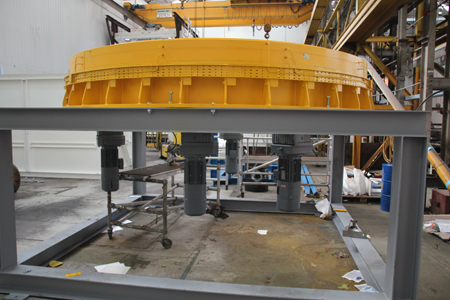
One example of where minimising the disruption to pedestrian flow is critical and hence the bridge operation and time taken to clear the bridge is of particular significance is the Clock Tower pedestrian swing bridge in Cape Town’s Waterfront development in South Africa. The movement of the bridge is already quite fast at 50 seconds rotation. This means that the next aspect to address is efficient clearing of the bridge prior to operation.
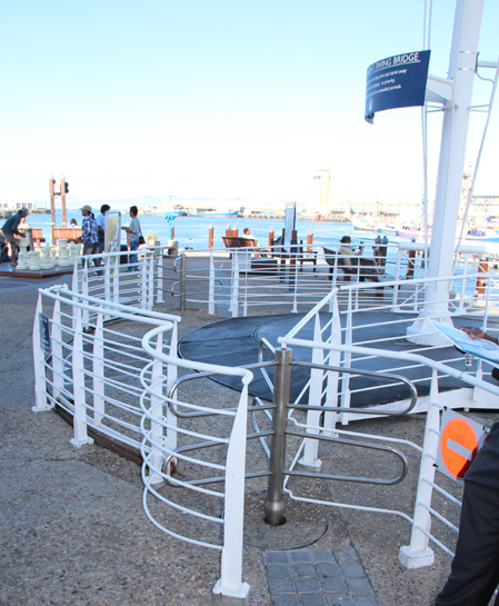
To do this the designer Henry Fagan & Partners, has employed turnstiles at the two ends of the bridge. This means that the operator can close the barriers at each end to stop anyone entering the bridge but the turnstiles allow those still on the bridge to exit enabling the bridge to be cleared much faster than having to wait for the inevitable rogue pedestrian who has ignored the warning lights and entered the bridge.
As the design process progresses, construction considerations also need to be addressed. Any mechanical equipment needs to be installed and set up to a high level of accuracy - fractions of a millimetre in some cases - whereas the structure itself will usually be constructed to an accuracy of millimetres and the civil works to centimetres. For this reason, the mechanical design must include relatively large amounts of adjustment so that the differing levels and build-up of tolerance and long-term settlement can be accommodated. Appropriate methods of adjustment may take the form of shims, packers, slotted holes or shear keys which are welded into place once final assembly and installation are complete.
As well as geometrical tolerances, other aspects that are less critical for static bridges, such as mass and centre of mass, are hugely important for movable bridge projects. For this reason, it may be beneficial to plan for trimming ballast to be incorporated at the tip of the movable span and/or within the counterweight, if one is provided. The Lower Hatea rolling bascule bridge in New Zealand is a prime example of where the location of the bridge centre of mass is critical to the successful operation of the span.
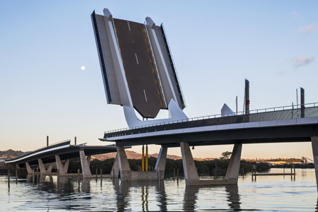
In this instance the counterweight is in the ‘hook’ at the end of the inclined mast. For this project both the horizontal and vertical position of the centre of mass were important because in the raised position what was a vertical distance from pivot to centre of mass becomes a horizontal one. Before any of the bridge pieces were assembled the contractor, McConnell Dowell, carried out a Monte Carlo simulation to understand the criticality of the deck mass and centre of mass measurement.
This allowed the contractor to be satisfied that the proposed method of measuring and weighing bridge pieces would result in an installation that did not require time-consuming and costly measurement and manipulation of pieces to get two axis centre of mass geometry. The counterweight was designed such that it could be adjusted and installed in pieces to enable the final balancing to be achieved within the tolerances required for the lift cylinders and the rest of the structural design. The nose ends of the two main structural members contain ballast that allowed fine adjustment of the balance.
Fabrication of the mechanical equipment and assembly of the electrical and hydraulic systems will take place at the same time as the civil and structural elements are being constructed. Before the electrical and hydraulic systems leave the works, a full series of factory acceptance tests should be carried out to ensure the functionality meets expectations. It is usually quicker, safer and more effective to resolve any issues at the factory than on site. A key period in the life of a movable bridge is its commissioning.
This is the period when all modes of operation should be tested, along with all reasonable failure modes, to ensure that the bridge will operate reliably from the start. Each movable bridge is unique and hence it is unlikely that the exact set-up has been built before. Even if the project is a duplication or part of a series of very similar or even identical bridges, small variations in mass or friction can impact on the operation of the bridge. Due to the critical nature of commissioning and the fact that it usually occurs at the end of the project when the programme is likely to be squeezed, there may be a benefit in including a fixed period of commissioning within the construction contract, to ensure that this critical activity is given the time it deserves.
There may also be a benefit in requesting a minimum number of successful consecutive bridge operations at the end of the commissioning period, to establish that the bridge is reliable before it is handed over and put into service.
As construction draws to a close and the handover of the bridge to the end user nears, one final, important step relating to long term reliability must be addressed. Training of the operators and maintenance staff must be effective in order to ensure that the day to day running and maintenance of the bridge is fully understood and that the various recovery methods and features that have been built into the design can be used to minimise any disruption.
Training by the installation contractor must be carried out, potentially over several sessions, to ensure that all of the end users in their various roles understand what to do and when. Maintenance is key and if this is not being carried out correctly then reliability will suffer. These training sessions also offer the end user a chance to ask questions and make what can be quite a daunting new task seem more manageable and achievable. The ultimate success of a movable bridge project is measured by its reliability and this is achieved through simple design and maintainability.
Both of these aspects should be considered from the start of the design process, where they can be most easily incorporated. Time should be allocated, potentially as part of the contract, to ensure that commissioning and test periods are given sufficient prominence and that the staff who will operate and maintain the bridge fully understand the functions and tasks that they will be carrying out throughout the life of the bridge.
Michael Thorogood is a director of Eadon Consulting