The announcement by Dutch 3D printing specialist MX3D earlier this year that its team intends to print a bridge over a canal in Amsterdam, unsurprisingly sparked international interest. The actual bridge construction event is still some way off, says chief technical officer Tim Geurtjens, and the team has a great deal of work to do in testing the material and the process itself, but he is confident that it can be done.
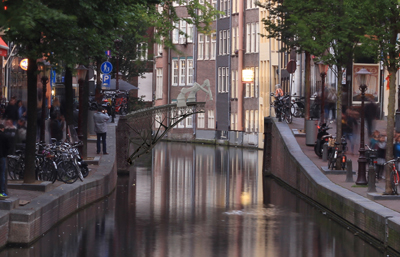
MX3D is seeking a canal site in Amsterdam on which to print its prototype (Joris Laarman)
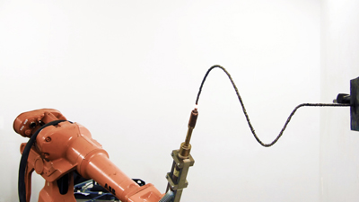
The conventional 3D printing process is much like traditional printing, with the print heads working from above and the main difference being that they print not only a 2D pattern but also add layers of material to create the height and add the third dimension.
Geurtjens’ firm makes multi-axis robots which are designed to print along the horizontal axis as well, and it is this which will enable them to work from each side of the gap to create the bridge structure. But working in this manner creates inevitable problems: “Gravity will pull on the material,” points out Geurtjens, “and we have to do more research to try and establish the right material properties, printing speed, material feed and so on which will enable us to counteract this.
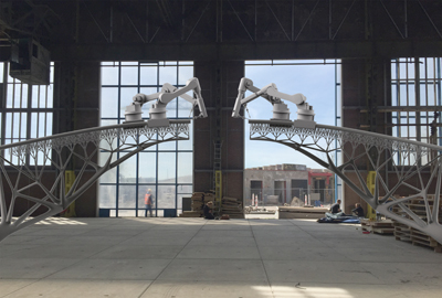
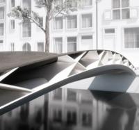
How the bridge construction might look (Joris Laarman)
“We can print in virtually any direction,” he says, “but when this is the case, there are lots more constraints that we have to consider.”
At the moment, Geurtjens says his team is working intensively with Autodesk to try and develop a more advanced topology optimisation in their Dreamcatcher software. This involves creating a custom-made version of the program to work specifically with MX3D’s printing process.
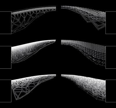
The idea is that the bridge designer specifies the space available for the structure, the forces it will have to carry, the properties of the material which it will be built from and so on, and the software then calculates the most efficient shape to meet those criteria. It does not matter how complex the shape is when you are dealing with 3D printing, Geurtjens says, as you are not bound by the restrictions of traditional manufacturing processes.
There is no confirmed location for the bridge as yet, simply that it will be over a canal in Amsterda. Geurtjens says he is in discussion with the city authorities to try and find a suitable location from several under consideration. “We do want it to be as short a span as possible,” he admits, “but this could be anything from 8m up to about 15m maximum.” He is keen for maximum publicity – a clear indication of his confidence in the process – and so wants it to be the most visible place possible, right in the centre of the city if he can.
The issue of available space at the site will be a difficult one; the team wants to have a visitor centre and workshops next to the bridge site, and it may be that the bridge itself is not printed in situ but made off site. The first year of the two-year programme that MX3D has set itself involves fully testing the capabilities of the technique. Once this is fully investigated and understood, the bridge design will reflect what it is possible to do. “The options are endless,” says Geurtjens, “the robot does have a building envelope but it can move on tracks so we can theoretically build to any size.”
His firm has already used this equipment for making large items of furniture, and for printing art works. He does not see any major difficulty in adapting it for construction of small bridges – and the change of direction from furniture to infrastructure came about quite by chance. “We were in San Francisco for a meeting with Autodesk, who have been involved right from the start,” Geurtjens recalls, “and we were doing some brainstorming the night before as to how we could showcase our technique on a large-scale project. We came up with the idea of a bridge because of the fact that Amsterdam is a city full of bridges!” Geurtjens put the idea forward the next morning and it got a very positive response.
At that point, he started to approach more companies, including contractor Heijmans whose staff are providing advice on the engineering and construction process, regulations and codes.
However there are definite limitations to the practicalities of in situ construction, so it is debatable whether the renderings showing robots printing a bridge over the canals of Amsterdam will actually be seen. The welding, or printing, process is the sensitive aspect; it uses a shielding gas in the same way as welding does, and it cannot be done in the rain – if you have ever been to Amsterdam you’ll appreciate this is could be a real obstacle. There is the issue of security and safety, the welding light needs to be shielded from view, and so on.
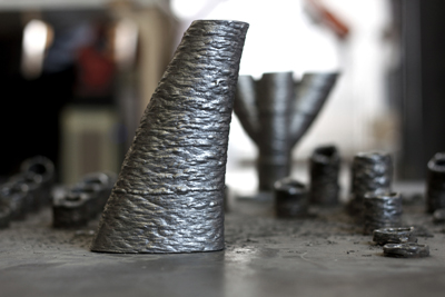
“We have already printed a 1.5m-span bridge,” Geurtjens says, “and now we are working on a 4m span to test the technique further. Following on from that we will print the first full-size bridge.” He predicts that by spring 2016 they will have a clear picture of the design; the team has announced that it will open its visitor centre in Amsterdam next month.
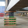
While under construction, the cantilever need to be supported on temporary support structures. Quality control is done by close monitoring – the robots are equipped with sensors that monitor the printing process constantly, and Geurtjens says that every time they print, they will make an extra length of material that can be cut off and tested.
Meanwhile the process is also being used to create lighter and more efficient structural connections – at this stage mainly for use in building facades and special structures. At the moment, however, the potential for similar applications in the bridge industry for 3D printing are largely restricted by the size of most manufacturing chambers, according to Arup senior designer Salome Galjaard. She is leading the team that has been working to optimise designs of structural connections for production by additive manufacturing, and has been able to reduce the weight of the structure by an estimated 50%.
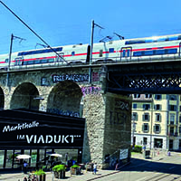
Initial research began more than two years ago when she was involved in the design of the lighting system for the Grote Marktstraat refurbishment project in the Hague, in the Netherlands. The system was built around three large tensegrity structures which were designed to act as ‘urban chandeliers’ above the street. The scheme which was proposed by the architect was an irregular structure and as structural engineer, Arup had to design all the elements, including the nodes. “There were about 1600 nodes, and they were all different,” explains Galjaard. “They were each about half a metre tall, and there were some 1200 design variations where the cables came in at different angles, directions and so on.”
On the project they were all made of plate that had to be cut and welded, but Galjaard, with her background in manufacturing, was convinced that there must be a more efficient route to producing them.
“No-one was really using 3D printing in the construction industry, no-one seemed to be even interested in using it,” she recalls, and she tried to find out how it was being used in the automotive and aeronautical sectors, but was not able to find anyone willing to share their knowledge.
After being granted some research funding by Arup, she began with a literature study to investigate the current state of the industry and the technologies available. Although the team’s first attempt to design a scale model of the node for production using additive manufacturing achieved a 30% reduction in weight, it had not been optimised for the process, nor taken into account any design rules for this type of manufacturing. Additive manufacturing – a process in which a metallic powder is melted by a laser beam and solidifies to form the final product – offers more geometric freedom than conventional processes, but still has limitations that must be considered in order to optimise the design, and these limitations are very different to the conventional ones.
“We wanted to ensure that the production process was quicker, cheaper and simpler,” Galjaard says, “so we had to learn about the additive manufacturing rules and redesign the node before we could make our first product.”
She recalls that when they made their first node model using this method, they did not make a big announcement, they just published a short item on the firm’s website. “It exploded!” Galjaard says. “Once people had it in their hands, they could see it, it totally changed their attitude towards what might be possible.
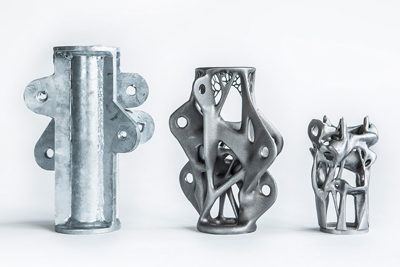
Left to right: the traditional form of connection and the two prototype designs by Arup
“But we realised that if we really looked at the functionality of the product and considered it in relation to the additive manufacturing rules, we could really adapt it even further,” she says. “The secret is not to start with topography optimisation – don’t just look at it in the context of weight reduction, you need to look at how the node relates to all the other elements, in this case the rods and cables, and consider how you can make the function more central to the design.”
In the case of the node the standard process of connecting the cable or rod to the node was onerous, and involved the use of a pin and fork and spanner arrangement, which were also heavy and added cost to the structure. The designers considered how they could integrate this function into the design of the node, and came up with a solution which requires only a threaded bar and nuts, which could potentially eliminate around 15,000 elements from the system.
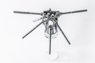
The node as it would be used with connectors (Arup)
Material considerations
With the additive manufacturing process still relatively new, it is vital that designers have an understanding of the impact the process has on the material properties, as well as ensuring that appropriate quality control procedures are being implemented. Arup devised a range of tests to investigate the material properties of the node it designed, expanding on the information supplied by the manufacturer.
Taking into account the evolution of the design and the context, 1.4404 stainless steel – equivalent to 316L – was selected from the standard range offered by the manufacturer. The selection was based on performance and durability requirements but also familiarity and experience in similar built environment applications.
The mechanical properties quoted by the manufacturer met the basic design requirements, and a schedule of production testing was compiled not only to validate the properties, but to expand on the physical and mechanical test data that was provided. The test schedule was developed to quantify some of the fundamental metallurgical properties of the material, resulting from the additive layer laser melting process.
The programme covered mechanical testing including, tensile, Charpy impact, and Vickers hardness; physical testing including verification of chemical composition (ICP-OES), dimensional characteristics and microstructure.
Samples were produced using the same powder batch, machine, parameters and finishing techniques as the finished node, although destructive sampling wasn’t possible due to the complex geometry of the finished node. Samples were produced in the vertical build orientation, representative of the node, and one set of samples was subjected to solution annealing heat treatment.
Test pieces were built to standard mechanical test piece geometries to avoid the need for machining and to ensure the test pieces were as representative as possible of the finished node.
Arup’s report pointed out: ‘Standardisation can only apply around the general parameters of the technology. As every item produced by AM is unique, it is necessary to quantify materials properties and performance on a case by case or project by project basis. By considering conventional products in the cast, wrought and fabricated condition, we had a basis to compare our results and expectations to attempt to validate the performance of our product.’
From the tests that were performed, Arup metallurgist Neil Perry confirmed that the mechanical properties achieved were largely in accordance with normal wrought product forms, such as bars, plates, sheets and tubes in annealed and mildly cold-worked conditions. All of the test results conformed to the requirements of relevant international product standards for comparative products, with subtle variations in typical composition and mechanical properties. The results were very encouraging in the context of the project and demonstrate that current selective laser melting techniques, applied to suitable materials present a valid technology for the production of components of satisfactory quality and integrity.