
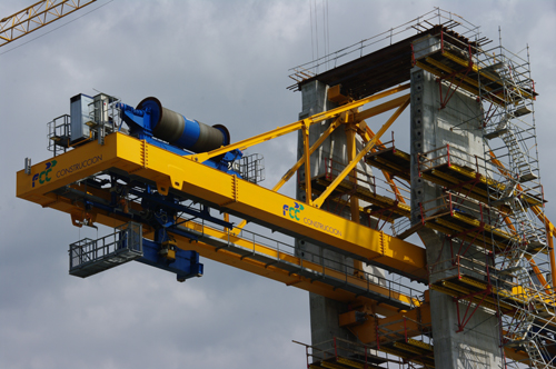
Close-up of erection equipment on one of the towers of the main crossing
The bridge is on transport corridor IV of the Trans-Europe Network which is designated as EN79 and links Germany to Turkey through Romania, Bulgaria and Greece.
Originally the scheme was approved as part of the treaty agreed for Bulgaria’s accession to the EU, but political issues and problems with access to land for construction and for sourcing aggregates resulted in delays to the programme. The project was officially launched in 2007 but the full opening - originally scheduled for two years later - is now expected to take place in summer 2012. Funding for the link is being provided by the European Commission via its ISPA programme - Instrument for Structural Policies for Pre-Accession - and the delays meant that an application had to be made to extend the deadline for completion, so that the funding would not be lost.
The river crossing is being built on a design-build contract by Spanish firm FCC Construccion, working with its design consultant Carlos Fernandez Casado, at a contract value of approximately US$147 million. The client’s engineer is a joint venture of Ingérop and High-Point Rendel, which is responsible for the independent check of the main bridge and site supervision.
The new river crossing connects the towns of Vidin, in Bulgaria, and Calafat in Romania. At this point there is an island in the Danube River, which makes a convenient stop-over for the bridge and enables it to be divided into three main sections - a low-level rail approach viaduct with 40m-long spans on the Bulgarian river bank; a single-cell box girder bridge with 80m-long spans over the non-navigable channel, and a four-tower extradosed bridge over the main navigation channel. The viaduct over the non-navigable channel is 612m long and has eight spans, of which all but one are 80m long. The main bridge has five spans; three spans of 180m, one of 124m and one of 115m. The low-level viaduct is a total of 400m long and serves to align the road and rail lines correctly as they approach the main crossing.
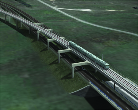
With the highway at ground level, the railway is raised above it and carried over one carriageway on to the centreline of the crossing. The highway is then raised up to reach the same vertical alignment, one carriageway on each side, as they enter the actual river crossing.
Under the design-build contract, the main design criteria set by the client were the minimum navigation span width and height - the choice of structural form was made by the contracting consortium.
Carlos Fernandez Casado says that crossing the river in one go is perfectly possible, but would result in an excessive structure with oversized towers and bulky struts, which would not suit the flat landscape and would be excessively expensive.
Crossing the river in two sections with a single tower in the middle, would create an inadequate division of the river. For aesthetic reasons, rivers have always been divided into an odd rather than even number of openings; such a subdivision would only be adequate if the shipping traffic was so great that two completely separate directions would be necessary. This would not just have to be the case at the bridge but also over a great length of the river. This requirement could not be met given that the river’s depth is not usually equal in all places.
Three openings produce aesthetic harmony in the subdivision of the river while meeting the shipping capacity demanded on this project.
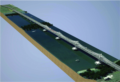
With regards to the bridge design, the intention was to establish a concept that could unify the entire superstructure of the bridge. CFC chose a central box girder with a constant depth of 4.5m and a width of 7.2m. The rail tracks run along the centre of the bridge, directly on the box girder, while the highway is carried on cantilever deck sections on each side, which are supported by inclined struts. In order to minimise the number of deck joints in the bridge, an integral design was selected, with a total length of 1,791m between the joints in the three abutments.
However, over the main arm of the river it would be impossible to span 180m with a 4.5m-deep deck. Hence two parallel planes of cables are used along the edge of the box girder, contributing to the support of the main spans, while also serving to separate the railway and the highway. This allows the same deck depth to be retained across the full length of the river. The two planes of cables are 8.5m apart, contributing to the torsional rigidity of the structure, and counteracting the highway loading.
The stays connect to H-shaped towers which are supported on the pier and extend through the deck to a height of 19.4m above deck level, where the saddles for the stays begin. The total height of the towers ranges from 39m to 45m above the pile cap; the height above deck level is 21.4m.
However, the use of cable-stayed spans can lead to problems of fatigue in the cables under railway loads. In order to control fluctuation in load variation in the cables under live load, CFC used a similar solution to that which was applied for example on the Cordoba Bridge over the Guadalquivir River in Spain. This solution involves placing two inclined struts below the deck to reduce the load fluctuation. They are carefully located so as not to interfere with the navigation channel requirement. The resulting deck support consists of the upper parallel planes of cable-stays and two struts in the lower section. These sections of the deck are being built by the free cantilever system using 4.2m-long, precast segments. No temporary support is placed in the river during the construction.
The cable stays have been designed to perform as an extradosed system, implying an important reduction in the stress range due to live loads. A number of different structural features contribute to this reduction. Firstly, the tower height is low, at around 1/10th of the span. The 4.5m depth of the deck is considerable when compared with a more classic cable-stayed bridge; the Cadiz Bay crossing for example (Bd&e issue no 61) has a 3m-deep deck girder for a 540m span. Two options were considered to limit the stress range in the cables; a variable depth girder or a constant depth girder with longitudinal struts; the latter was chosen as being more effective.
In addition to the choice of an extradosed cable-stayed span for the main crossing, another notable aspect of the bridge design is the width of the main deck. Carrying four lanes of road traffic - two in each direction - and a footway, in addition to a single-track railway along the centre of the structure, the deck of the single-cell concrete box girder has a total width of almost 31.4m.
The box girder itself is 7.2m wide by 4.5m deep over the full length of the bridge, maintaining a constant soffit profile across the entire structure. The girder has bottom slab 7.2m wide and a thickness which varies from 0.45m to 0.75m; the webs have a constant thickness of 0.5m which increases to 1.3m o