Over the last 15 years the expansion of the high-speed rail network in China has been rapid. Since construction of the first high-speed passenger railway between Qinhuangdao and Shenyang began in 2000, launching machines have been widely used, especially for the full span viaduct construction method. In 2006, the first 900t-capacity gantry was used for full-span bridge construction on the Beijing-Tianjin high speed railway, and since then a whole range of launching machines has been developed for the full-span erection of prefabricated bridges, such as the launching gantry with longer underbridge, launching gantry for double box beam, special launching carrier with underbridge for travelling through tunnels and so on.
Launching gantry for full-span method
Launching machines are always customised to suit the specific bridge design, construction conditions, structural dimensions of beams and so on and the machinery supplier can only begin the design after receiving these details from the client. As a result, launching machines differ depending on performance, dimension, lifting capacity, functions and so on; even if a bridge project needs multiple launching machines, the supplier may design different erection solutions and the launching machines may vary in structure, operation and controls.
When launching gantries were first used, many owners amortised the machine’s value for a single project, hence machines were not generally reused because there was little chance that they would be suitable for other bridges, in particular in terms of schedule, time period and location. Usually only the salvage value of the material would be assessed.
But since the boom in bridge construction in China, many owners now want to reuse their launching machines, and the equipment represents a fixed asset in the finances of the project. Many machines have been reused in the last decade on different job sites in China, including machines in which parts or components have been replaced or upgraded for the new jobs. Some machines have been reused for up to five different projects.
Due to the size of the machine, it must be transported in separate components and assembled for commissioning at the new job site. When a launching machine is to be reused, a number of items have to be considered before it is moved; the technical analysis and cost evaluation for reuse; checking and repair of parts and components of the used machines; safety evaluation and review of the safety system, and re-commissioning.
Evidence over the last few years demonstrates that many of the accidents involving launching machines were due to lack of attention to one or more of these aspects. Preparing a launching machine for reuse may be more complex than designing a new one, and it needs particular attention when the machines are to be reused by different clients or the machines come from various suppliers.
More than a hundred launching gantries have been ordered for use in China over the last 15 years and these have been reused multiple times. Manufacturer Beijing Wowjoint Machinery Company compiled statistics relating to 52 launching gantries it supplied or was involved with over this time.
The reuse of launching machines is ubiquitous in China; more than 70% of the 52 investigated had been used twice or more; 37% had been used at least three times. Most of the remainder were already in their second use or due to be so in the near future.
On average, launching gantries erect around 730 spans in a lifetime, with almost 40% of gantries erecting more than 1,000. More than 70% of launching gantries have a service life of more than four years, suggesting that the majority of machines must be evaluated and require an intensive inspection for maintenance and safety.
Of these, the vast majority - more than 80% - have a capacity of between 800t and 950t, and are mainly used for construction of high speed rail viaducts.
Meanwhile just 18% of launching machines are estimated to have been reconfigured for reuse, indicating the need for technical analysis and recalculation for the reuse of launching machines.
Analysis and checks must be carried out before equipment is reused, in order to identify any technical problems and analyse the machine’s applicability for the new site. Timely maintenance, technical upgrades or reconfiguration for new working conditions are necessary to avoid problems on the new project (see examples at the end of the article).
Special considerations may include construction conditions, the climate, and specific bridge conditions such as working next to existing lines. Professional design personnel must be employed to carry out technical analysis so that solutions to these special conditions can be identified.
Most of Beijing Wowjoint’s launching equipment is designed to European standards, with some designed according to GB/T 26470-2011 General specification for launching machines and GB/T 3811-2008 Design rules for cranes.
Based on the working conditions of launching machines, the service period for any machine is limited to 15 years. Generally the designer selects a theoretical service life for mechanical equipment of about 1,600 working hours during the 10-year service period. The working class selected overall is A3 with the mechanism working class M4 being applied to the machine.
But in a single mechanism, different parts may be designed for different service lives; for example, the design service life of bearings in the reducer is normally one or two classes lower than that of gears. Therefore in theory, the bearings of the reducer will have to be replaced once or twice in order to achieve an equivalent service life to that of the gears during the same period of use of the reducer.
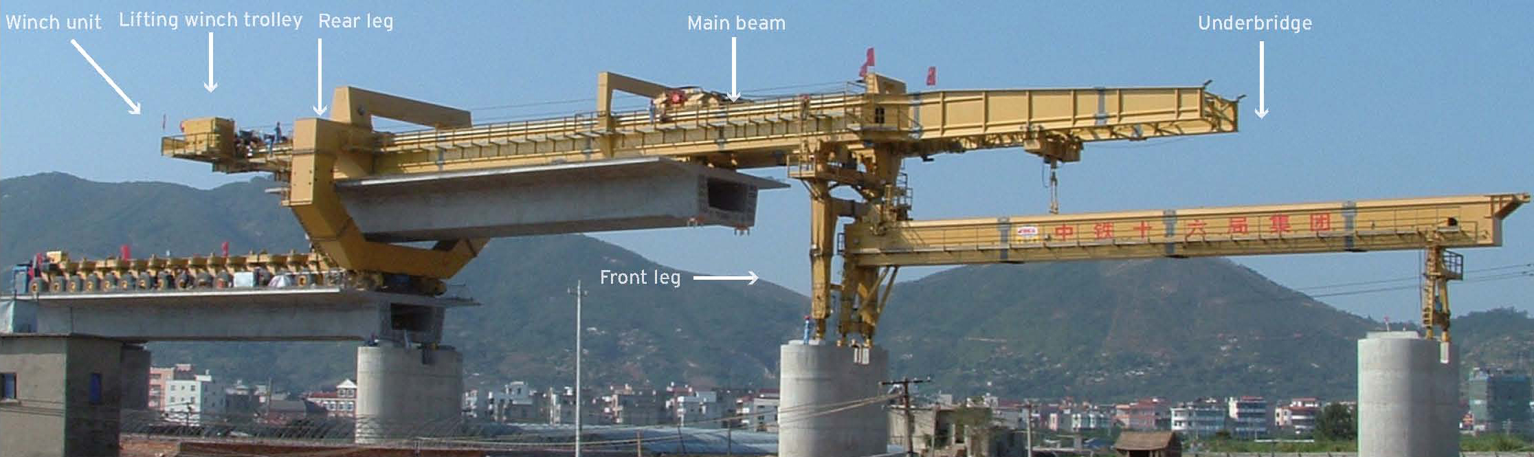
Launching machines generally fall into two categories; the special launching carrier and the launching gantry, depending on the function of the structure and the launching procedure.
The working cycle of a launching machine normally follows this procedure; the machine launches itself into position; the beam is fed from the rear deck; the beam is positioned onto the piers; the machine launches itself again for the next construction cycle.
During erection of each span, each part of the machine is brought into use at least once, but during their operation, the working time for similar mechanisms during different types of operation can differ between each cycle.
One example would be a special launching carrier which is carrying out three jobs in once cycle; lifting the span at the yard, carrying the span to site, and erecting it at the job site. Some parts such as the beam derrick and pulley block of the main launching mechanism, lifting mechanism and beam lifting winch are in operation for more than three hours during each erection cycle. As a result, the service life for these parts during this type of operation is less than 2,400 spans.
However in the case of a launching gantry which would be combined with a beam transporter to work on the erection of bridge beams, the main launching mechanisms will be at work for just two hours during each working cycle. In this case, the service life of the main mechanism will be more than 2,400 spans.
Calculation of the total design service life of the mechanism is normally based on the service life of the main components of the machine. The service life of other parts of the machine may be shorter than that of main parts, so these must be inspected, maintained and even potentially replaced at intervals throughout the total design service life of the machine.
Parts of the lifting mechanism that must be considered include the wire rope, lifting bars, tensioning screw bars, drum bearings and reducers – service life for the wire rope could be between 400 and 1600 hours, whereas the life of the lifting bars would be measured in number of spans, usually around 600 as a reference value.
Tyres, wheel bearings and reducer are considered when assessing the service life of the driving mechanism – there are many different factors that affect the tyre service life, including climage, storage, specification and service conditions such as load, speed, inflation pressure, maintenance and pavement behaviour. Operating mileage could vary from 20,000km to 50,000km on this basis, whereas the service life of the other components is generally measured by hours of operation.
The service life of the main structural steel elements is usually measured by the number of cycles under certain conditions.
Since most concrete box beams lifted on projects are of similar size, the service life of the mechanism will be reduced if the weight of these beams is close to the maximum lifting capacity and the machine is working in conditions exceeding mechanism working class M4. But often contractors in China have to speed up erection to meet shorter construction periods and hence launching machines may be in operation for longer days. They may erect more than three or four spans per day, meaning that the working hours of the main lifting system could exceed four hours a day. These main mechanisms will certainly have exceeded their design working class, hence their service life will be reduced.
Intensive daily and periodical inspection of all mechanisms is necessary once the working time reaches more than half their total design service life – that is, when the machine has erected 1,200 spans. Some parts with lower service lives should be repaired or replaced.
Full inspection and maintenance of the machine is indispensable once it has completed erection work on one project and before equipment is rebuilt on the next job. Any parts with defects should be returned to the manufacturer for repair or replacement.
The condition of the equipment is one aspect, but its suitability for a new project is a different aspect. The difference in structural requirements and geological conditions between roads and railway lines, and between high speed and local railways, results in a variation in the design of concrete beams, piers, abutments, bridge decks and tunnels.
Before engineers can confirm whether a launching machine is suitable for use on a different project, the functions, performance parameters and dimensions of the machine have to be checked against those required on the new project. When a project includes special working conditions, more detailed research must be carried out and each and every step of the procedure must be checked.
If the special requirements cannot be met by the gantry in its current form, the end user should contact the designer and manufacturer of equipment for a new design and upgrade of the equipment before the reconfigured machine is taken to the new site.
Such special construction conditions might include erection on a tight radius, where the bridge has a radius of curvature of less than 2km for full span erection, or less than 600m for segmental construction; bridge erection after passing through a tunnel, where the tunnel has a radius of less than 6.4m; erection in a tunnel entrance, or inside the tunnel itself, where the distance between bridge abutment and tunnel entrance is less than 40m; erection on a gradient of more than 2%; erection on a continuous uphill gradient of 12% or more, and for longer than 2km; a project including a distance of more than 15km for the hauling of the precast beams; a project where the gantry passes through a tunnel of 8km or more; or bridge erection in opposite directions, where the equipment needs to change direction.
Special conditions relating to the bridge or viaduct could include a bridge with a variable abutment top; a bridge with pier heights of more than 40m; variations in the width, height or transverse centre distance of lifting holes for the deck dimensions; erecting various spans of bridge beam and disconnecting these beams; erection adjacent to a continuous bridge beam or combined bridge beam, or lifting of precast beams from alongside the bridge deck.
Special conditions relating to an existing structure might include a situation where the distance between deck edges of two parallel bridges is less than 2m, or between the new bridge and existing railway or road is less than 10m. It could also relate to construction in a downtown area, or above a busy railway or road.
When a launching machine is intended to be relocated to a different region or country, it is important to give special attention to the potential for problems caused by a change in climate or working conditions. For example if it is relocated to an altitude of more than 2,000m this could affect the combustion of the engine, leading to a high level of carbon deposits in the cylinder with consequent reduction in power and service life of the engine.
Similarly where the new site is in a cold region with temperatures lower than -20°C, this is close to the minimum for some electrical parts. Electrical parts working at this critical temperature are likely to suffer more failures, or hydraulic parts may suffer through the hydraulic oil becoming contaminated with water which subsequently freezes in the valve element and oil duct.
Areas that often experience gusts and high winds of up to 72km/h put the stability of the launching machine at risk. No erection work can be carried out when the wind speed is above 60km/h. In such conditions, any anchoring devices for the lauching machine must be carefully checked before it is put into use. In areas that suffer typhoons, additional anchors must be designed for the machine.
In desert areas, windy and dusty conditions frequently number more than a hundred days per year, and sand storms can even occur at the job site. To prevent dust from causing problems, air filters must be replaced frequently, and the rotation shaft and wire rope should be treated with dust protection.
When erecting precast beam on piers taller than 40m in mountainous areas or on the sea gulf, it should be taken into account that gusts of wind greater than 62km/h are possible; far too dangerous for erection to take place.
If these issues are considered and reviewed in advance, the safety record of second-hand equipment can be improved. The equipment must be assessed for the new working conditions and if it does not meet the requirements, should be reconfigured in advance to eliminate the danger that the construction site has to be shut down, and reduce the risk of accidents such as overturning of the machine. Evaluation of an existing machine largely focusses on a review of the equipment archives and check of the equipment conditions; once these have been carried out, an evaluation report can be issued.
Equipment archives may include drawings, operation and maintenance manuals, factory certificates, load test reports and certificates, trouble-shooting records, maintenance records, operation records with oil and water filling, reports on accidents, technical upgrade records, photos and so on. Technicians should be commissioned to undertake a full-scale inspection of the equipment to identify any wear or defects of mechanisms and to test all functions, especially in the case of any launching machines which have completed more than 1,000 spans.
The evidence examined suggests that the majority of those reusing machines in China do not consider it necessary to analyse and evaluate the used equipment; they generally assume that the machines will work just as they have on the previous site and that even the technical reliability need not be reviewed. But reuse of launching machines often involves greater risk since the machine’s performance can be changed once it has been reassembled; defects in parts, particularly hydraulic and electrical ones, may disable operation of equipment, or increase the potential safety hazards; the reliability of the safety systems decreases; and the applicability of the machinery may not match the requirements of new project.
Every mechanical, electrical and hydraulic device used on this type of large machine is indispensable for proper operation. Without thorough management and inspection, there is a risk that the personnel responsible for the work will not have the appropriate skills and knowledge to carry it out properly. This could result in protection devices not being operational, key parts of the mechanism not being propertly inspected, electrical circuit connections incomplete, and so on.
In addition to the safety risks, technicians working for unqualified companies may not have the appropriate liability cover to work on heavy duty launching machines. In the event of any mechanical damage or an accident, this will make the subsequent legal dispute and accountability very complicated.
Analysis of the records relating to these 52 launching machines highlighted a number of key items for inspection. Most launching machines have eight lifting bars which are used for lifting concrete beams during construction. The bars have threads on each end and mainly bear tension, so the start of the thread is the point at which the tensile stress is focused, and which bears the cyclical tensile stress during construction.
When the cyclical stress ratio is fixed, the fatigue strength of the metal component is reflected by stress on the component and the cyclical index. Test results show that the smaller the stress ratio of the metal component, the lower the fatigue strength and the more easily fatigue damage occurs.
The stress ratio of the bar is very low before and after beam lifting and installation. Theoretically, fatigue damage is most likely to occur at the start of the bar thread, where the stress is focussed, and this is proved to be the case. Consequently it is important to use non-destructive testing methods such as visual testing, magnetic particle inspection and ultrasonic testing to examine the lifting bars. Such inspections should be carried out when the bars have lifted 200 beams, and the bars should be replaced after the machine has erected 600 spans.
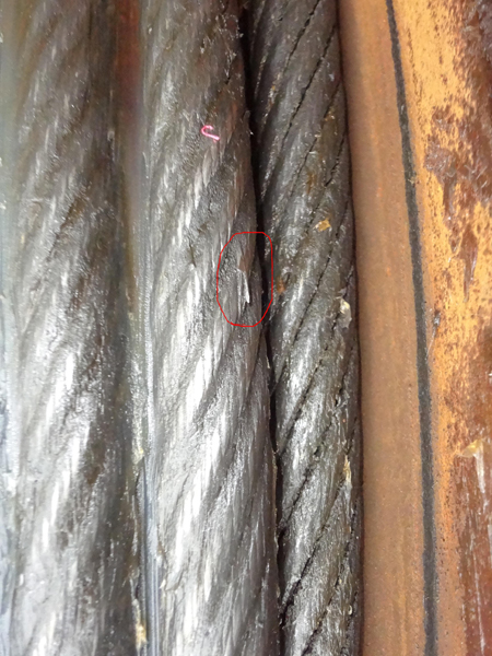
Wire ropes are also key components of the lifting mechanism. The most common damage to ropes is not caused by wear but by external damage, hence any inspection should focus on examining the external condition of wire ropes when the machine is being assembled, moved or transported. Besides any maintenance or replacement of the ropes as dictated by technical codes, if any external damage of the ropes is discovered, the degree of damage should be assessed.
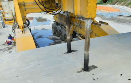
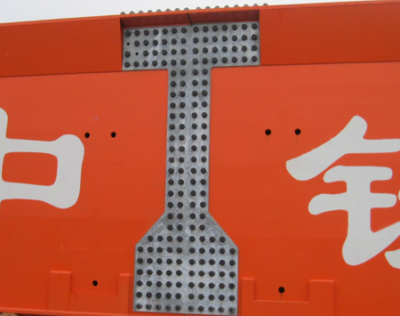
The main girders of most launching machines are connected by high strength bolts and the use of friction surfaces on the girder. By pre-tensioning the high strength bolts, friction on these contact surfaces balances the external loads, and the load capacity depends on the friction coefficient of these surfaces, which is clearly affected if the surfaces are dirty.
But the examples studied revealed that in practice, no effort was made to clean or protect these friction surfaces when the machine was dismantled and reassembled. Oil and dirt was left on the friction surfaces, which resulted in sliding of the surfaces soon after the start of operation, and also created abnormal noises at the joints during the construction procedure.
Generally speaking, when the launching machine is to be reused the connection surfaces of the structure joints should be sand blasted and a new layer of skid-resistant material should be applied.
.JPG)
Due to low frequency of lifting, it may be sufficient to replace only a third of the high strength bolts on the joints of the main structural parts when the machine is reused for the first time, but when it is reused for the second time, all the high strength bolts on these joints should be replaced.
The machine’s safety protection systems are vital to prevent human error causing damage to the machine or accidents. Before any reuse of the equipment, all the safety functions should be tested to confirm that they are working correctly.
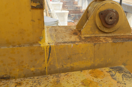
The safety brake on the winch, also known as the emergency brake, stops the drum rotating if the drive shaft of the winch fails. In the practical application, the gap between the brake blocks and the drum is sometimes too large, or there is oil contamination on the friction surfaces between the drum and brake blocks; both problems which can prevent the safety brake from working. These problems must be addressed if discovered during inspections. Finally all main welds should be visually inspected to check for any cracks or visible defects.
A number of parts usually need to be replaced or replenished each time the launching machine is moved and reassembled; high strength bolts, hydraulic oil, lubricating oil, hydraulic filter, engine machine oil and coolant, and engine filters.
The decision to finally scrap a launching machine should be taken after careful consideration and analysis based on extensive inspections.
Whether or not a machine should be scrapped will depend entirely on the evaluation of its design parameters and current condition, since there is no relevant code or regulation governing it.
For a machine in working class A3, combined with class of use U1 and load spectrum Q4, the expected working duration of the launching machine is usually seven to 10 years, if it is not in frequent use. This service life will vary if it is used for a different purpose, with a different regularity or under a different loading, for example.
However the evidence demonstrates that most launching machines are exceeding the U1 usage for more than half of their working time, which will reduce their overall service life.
Based on this situation, inspection times of launching machines should be more frequent, and the inspection scope should be extended, if the launching machine is used for longer than four years, if it erects more than 1000 spans, if it is reused more than twice, or if it is damaged during construction.
A complete inspection and technical review on such a machine should be carried out by fully qualified technicians, and its mechanisms should be returned to the factory for repair if necessary, to ensure reuse safety of the equipment.
If the main parts or components of main mechanisms – the lifting mechanism, carrier driving mechanism, winch trolley driving mechanism and so on – are found to be damaged, or multiple fatigue cracks are found on the main load-bearing metal structures and extensive cracks are found on the main load-bearing welded joints, scrapping should be considered.
In the international market, some purchasers require a buy-back clause, where the buy-back price is usually 10%-15% of the contract value of new equipment, after the equipment has been used once. This price is considered to be the discard value of a used machine. However in China, there are no uniform criteria for calculating the depreciation of launching machines; sometimes it is based on the service period of the machine and the duration for use is usually five years; other times depreciation is based on the number of spans a machine has erected, usually 1500. Under normal circumstances, the discard value should be based on the market price of the recovered steel multiplied by a coefficient of 1.05 to 1.3. Further discussions are still needed to develop an agreed and fair method for calculating an accurate discard value for launching machines.
Yabin Liu is chief executive officer and Fuchun Yuan is chief technical officer of Wowjoint Holdings
Good and bad practice - examples
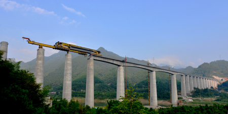
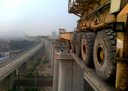
The Chinese construction industry has plenty of examples to demonstrate the problems that occur if recommendations for proper reuse of machines are not followed. On the Gansu-Qinghai section of Lanzhou-Xinjiang high speed railway construction, the 900t special launching carrier designed for passing through the tunnel was reused under both special construction conditions and special climate conditions.
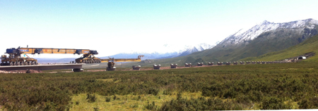
The construction conditions included both long-distance transportation and continuous uphill construction (above), with the minimum haul distance between the first erection site and the yard being 11km and a maximum distance of 15km between the last erection site of the second bridge and yard. The viaduct had more than 3km of continuous longitudinal slope with a gradient ranging from 20% to 8%. The yard was located at an altitude of around 3,300m for the first bridge and 3,350m for the second.
A machine which had already erected more than 350 bridge spans was relocated to the new job site, but without any adjustment to its power units. Plateau anoxia prevented sufficient oxygen from entering into the cylinders of the two Deutz engines and the power of the diesel engine declined considerably. Poor combustion inside the cylinder was exacerbated by operator who subconsciously continued to rev the accelerator, resulting in the exhaust pipe of the engine overheating to become red hot. After just a couple of days of work, one of the two diesel engines was damaged when the piston seized.
Another problem was caused by using the launching carrier in a long tunnel; the poor ventilation resulted in the service life of the air filter being reduced. In the meantime, bad ventilation also prevented proper combustion, resulting in serious carbon deposits in the cylinder, a decline in power and reduction of engine service life.
The damaged engine had to be replaced; only once the operation of the two diesel engines had been improved by reducing the engine rotating speed and applied power, could erection work continue.
In other example, a 900t special launching carrier originally designed for passing through a tunnel was to be reused for different working conditions at Zhengzhou Airport railway in China. The maximum design curve radius on the new bridge erection was 1,600m; shorter than the designed minimum radius of 2,000m. The machine had to be reconfigured with a connecting beam of wheel groups, upgrade of the main roller, new anchorage system and so on. Also the lifting beams were replaced because the transverse centre distance between the lifting holes on the new concrete box beam was 6m, compared to 3.4m-3.8m on the previous job.
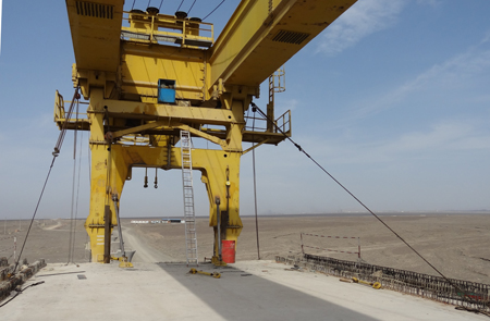
Another example (above) from the Lanzhou-Xinjiang high speed rail link was for construction of a bridge on a section of railway crossing the desert of the Turfan Depression, where gusts of more than 70km/h can occur. A 900t launching gantry from a shorter bridge was selected; many of its parts were renewed and it had to be equipped with extra anchor devices to the front of the machine and the underbridge supports so that the entire machine could be anchored to improve its stability. Extra dust caps had to be fitted to power units and main control boards, and replacement of oil and air filters on the engine were required.
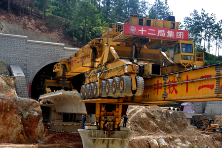
One particularly success reuse (above) involved two 990t special launching carriers which had been used for construction of the Hunan high speed rail projects in Korea, and were reused in China for the Hu-Kun high speed rail. It was clear that these special launching carriers would not work for the erection of the Chinese high speed rail project in the mountainous area, since it was based on a 32.6m-long span with 900t concrete beam compared to the Korean projecct of 35m span with 990t concrete beam. What’s more, the Chinese pier head was much smaller than the Korean design, and the bearing bases were also different. In addition, the Chinese job site was in a mountainous area and the launching machine had to pass through tunnels to erect the concrete beam at the tunnel exit and entry.
The machines were reconfigured when they were relocated to China and many new parts had to be designed and fabricated. The main structure of the carrier was partially modified to make the machine lower to allow it to move within the tunnel and to build shorter spans.
The underbridge of the machine was modified in length and its platform blocks were reconfigured. All of the lower parts on rollers were changed to suit the pier head dimensions of the Chinese bridge and the electrical and hydraulic systems had to be amended and renewed on PLC programs.