A new bridge for Reunion Island in the Indian Ocean is in intended to sit lightly on the island's fragile environment. Report by Jean-Emile Croiset, Jacques Ryckaert, Gregory Viel and Alain Spielmann
A new road which will connect the towns of Saint Paul and Etang Sale on Reunion Island has to cross 100 ravines, some of which are very deep and cannot be accessed from below. Because of the unusual topography of the island, four exceptional bridges, two cut and cover tunnels, a 300m-long twin tube tunnel and 20 standard and 20 non-standard structures have to be built for the new route.
The contract for the design and construction of the bridge over the Grande Ravine, which is one of the four exceptional bridges, was awarded in 2002 to a joint venture of consultant Setec TPI and architect Alain Spielmann.
The structure is notable because of the physical dimensions of the breach: it is 320m wide at natural ground level and extends to a depth of 170m. The steep slopes on each side, and the depth of the ravine prohibit any construction work from below. This constraint was particularly influential on the design, as were the need to respect the environment, and to design a structure that could resist severe weather.
The location of the island, in the south west of the Indian Ocean, puts it on the trajectory of tropical depressions and cyclones. Hence it was essential for the designers to take into account the risk of cyclones, both during construction and during the operation phases.
In terms of environment, the main consideration was the need to protect the Baillon's Puffins, an indigenous species which nests in the ravine. The risk of these birds colliding with the structure was considered to be higher for smaller bridge elements - this factor led to the elimination of all cable-supported bridge solutions. However, temporary suspension or bracing systems are permitted for a limited amount of time, as long as the risk to the birds is taken into consideration.
The sides of the Grande Ravine are made up of alternating metric banks of basalt and volcanic slag of average quality. The general dip of these banks is about 15o in the downstream direction. The admissible stress of the foundation terrain depends on the horizon involved: from strong on the basalt banks to average or even weak for the volcanic slag. Consequently a 'light' structure with foundations at a distance of about 25m from the cliffs of the ravine was developed.
The design competition requirements demanded a structure that would blend into the site, without disturbing either the fauna or the flora. It seemed highly desirable to propose a steel structure with a light deck, which would be easy to launch, and have a constant height.
The structure consists of a 288m-long steel box girder with orthotropic plate, which is to be launched from both sides and connected at midspan. Intermediate supports will be provided by two high-performance prestressed concrete braces inclined at 20o to the horizontal. The braces will be rigidly fixed into counterweight abutments at the base and maintained at the end by external prestressing cables inside the deck. The abutments are founded on superficial footings at the rear under the counterweight and on a large diameter concrete pile at the front.
The longitudinal profile of the structure slopes by just 0.5% from one bank to the other, and it has a straight alignment. The cross-sectional profile is roof shaped, with an inclination of 2.5%, and the single deck has a roadway width of 18.6m.
Braces built into foundations that are themselves buried in the rock of the two banks are used to support the bridge. This proposal, with its steeply-inclined braces, is derived from braced bridges, but with more slender proportions. This is intended to create a dynamic aspect which requires very little space, enabling the environment and the site to be preserved. The height of the deck was minimised, and its footprint on the two cliffs reduced as far as possible.
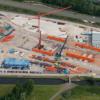
Contracts were signed at the end of last year for the US$54 million project, with Dodin/Vinci Grand Projets carrying out the concrete works and Eiffel as the steel contractor. Work on site started in April 2006 and is due for completion in November 2008.
Once the general earthmoving and abutment foundations have been built, the braces will be erected by cantilevering them out from the abutments. A temporary stay to connect the head of the brace to the abutment and launching of the deck will be installed. This stay is intended to counteract the bending moment of the brace, thus limiting the quantity of prestressing it requires. One half of the deck will be assembled on each bank, and then launched up to a position slightly beyond the brace. Once it is in this position, devices will be installed on the abutment to ensure static equilibrium. The second launching phase will then be carried out with the deck being launched almost to its final position, ready for the two sides to be connected. This phase is critical - it must be carried out quickly and in appropriate weather conditions; at this position, the structure will be very sensitive to high winds. A temporary connection will be put into place first, designed to withstand a ten year wind outside the cyclone season. The tension in the temporary stay at the head of the brace will be adjusted in accordance with the progressive increase of the deck support reaction. Sliding supports mounted on a temporary structure at the head of the brace will make up the upstream temporary support. The permanent hinge at the head of the brace will be installed during the launching operations, transported over the partially-launched deck. The structure of the hinge will then be welded to the deck once launching is complete, and the deck will be vertically connected to the abutment.
On each bank in succession, the hinges at the head of the brace that were installed during launching and welded from under the deck will be progressively loaded during an operation combining the partial tensioning of the final stay cables, the partial removal of the launch support and the partial detensioning of the temporary stay cables.
At the end of this operation, the temporary stay will have been transferred from the head of the brace to the interior of the deck, to become a permament stay, thus preserving the limitation of the bending moment of the brace.
Once this is complete, the ends of the deck will be jacked up vertically by 500mm and the final supports of the deck on the abutments, as well as the final transversal abutments, will be installed. The twin objective of this process is to relieve the moment in the deck at the braces and increase the positive reaction of the deck on the abutments under permanent load.
The deck is designed as a steel, multi-tubular streamlined box girder with an orthotropic slab. It is straight, with a constant slope of 0.5%, has a constant height of 4m, except at the support shoes of the hinges, and is 19.9m wide. It has a total length of 288m, with the braces connecting to the deck at approximately 73m from each end, creating a 140m central span between them. S355 steel is specified for the normal zones and S460 steel for the reinforced zones near the hinges.
The deck rests on the braces by means of the hinges. At the abutments it rests on classic sliding supports which are fixed in the transverse direction. The permanent stays are inside the box girder and connect the reinforcement zones at the hinges to the abutments. They are only connected to the deck at the hinges; the sheet metal panels are cut to allow them to pass without being deviated. Hence the cables are only deviated inside the abutments.