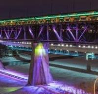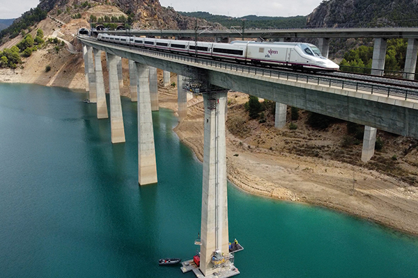
Train passing over Viaducto Del Istmo during the works (Freyssinet)
When a routine maintenance inspection revealed the bearings of the Viaducto del Istmo’s key piers were exhibiting excessive rotation, threatening both structural integrity and high-speed railway operations, a swift and innovative solution was imperative.
With the bearings of its first, third, and seventh piers compromised, the stakes were high for Spain’s Railway Infrastructure Administrator (Adif-Alta Velocidad) to orchestrate a replacement without disrupting the bustling railway traffic.
The bearings of the viaduct’s first, third and seventh piers had been found to have rotated excessively, which caused their pots to make contact with their respective stainless-steel sheets, thus deforming the stainless steel and impeding the free movement of the bearings. The national Railway Infrastructure Administrator awarded their replacement to civil and structural engineering specialist Freyssinet. The replacement was carried out between July 2023 and November of the same year.
The viaduct is located in the area of the Contreras Reservoir in the Spanish municipality of Villargordo del Cabriel, approximately 110km west of Valencia. The crossing features a curved layout with a reduced radius, enhancing its integration into the surrounding natural environment. The 830m-long girder bridge is approximately 80m-high at its highest point and comprises 12 spans with a maximum length of 66m. It has 11 hollow rectangular piers of varying heights between 21m and 71m made of reinforced concrete.
During the pre-operation site inspection, Freyssinet's technical department encountered an unforeseen challenge: the deck’s diaphragms were displaced and almost misaligned with the bearings. This posed a risk of introducing loads outside of the diaphragms while positioning the jacks for the replacement. To tackle this issue, engineers adjusted the design of the new bearings, devised a plan to cut the existing sliding plates, and scheduled the operation during the summer months. The higher temperatures would lead to greater expansion of the deck, allowing its most reinforced part to align more centrally with the axis of the piers. As a result, the jacks could be more accurately placed under the deck diaphragms.
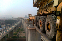
As the third and seventh piers are located in the Contreras Reservoir, the engineering team installed a scaffolding system anchored to the pier and deck and built a work platform around the piers. All materials for the in-water piers had to be transported by boat and lifted to the top of the structure via a lifting system comprising an elevator and two electrical hoists, each with a load capacity of 2,5t. Each lift took approximately 15 minutes, estimates Abel Medel Ramírez, project engineer at the technical department of Freyssinet Spain. As the supply of new material or tools was so time consuming, any changes to daily planned works had to be carefully considered by the site manager and the foreman beforehand. Additionally, the water level of the reservoir was expected to decrease around 15cm per week during the summer, so it had to be carefully monitored, “We were afraid of not being able to reach the scaffolding,” says Medel Ramírez.
![]()
Lifting materials to the replacement site at the top of the pier (Freyssinet)
As the bridge could not be closed during the project, the engineering team had to account for the live traffic loadings during the replacement operations. While the higher vertical loads could be accounted for simply through the use of more jacks, the project team also had to accommodate horizontal loads from the rail traffic during the bearing replacement. “This requirement led to the decision of installing shear keys,” says Medel Ramírez. “Usually these devices only allow vertical displacement of about 10mm, so we requested a modification to allow for a 20mm displacement,” says Laura Benito Gutierrez, site manager at Freyssinet and of the Viaducto Del Istmo site. The plan was to anchor the shear keys to the centre of the piers and the deck to allow the bridge to expand longitudinally while preventing transversal movement. The three shear-key devices that were designed, one per pier, were also planned to remain on the viaduct permanently.
One of the installed shear keys (Freyssinet)
Alternative solutions, such as using a steel frame within the pier to contain horizontal loads, would have presented multiple challenges. Installing the frame outside the pier would have complicated access and disrupted scaffolding, while an internal installation would have obstructed access to the bearing replacement area. The large dimensions required for the frame would have also posed a problem. According to Medel Ramírez, a steel frame roughly twice the size of a shear key would have been needed to make the design feasible.
The decision was made to replace the old bearings with the most advanced and durable spherical bearings currently available. Due to the lack of space for the installation activities, Freyssinet custom-designed each bearing to fit its specific location.
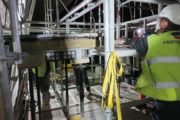
For the replacement of the bearings on Piers One and Seven, the crews first transported the materials by barge to a pontoon at the base of the pier. The materials were lifted to the working area at the top of the pier with the elevator and electrical hoists. Holes were then drilled into the deck and the pier where the shear keys would be fixed. Installing the 800kg heavy shear keys required inserting 16 prestressed bars per pier. The limited distance between the pier and the deck prevented drilling upwards, “So we needed to work from inside the deck and make these holes to be able to connect the masonry plate to the deck and to the pier,” explains Medel Ramírez.
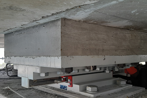
The original sliding plates were cut to install the lifting jacks. A total of 16 hydraulic jacks weighing 115kg each were installed around each bearing. The jacks, with a load capacity of 400t and a displacement capacity of 50mm and featuring a sliding system to accommodate the thermal movement of the bridge, were placed in the longitudinal direction on both sides of each bearing.
The structure was then lifted and the old bearings were extracted via manual hoists tied to a frame that was custom-made for the project. After removal from the pier, the bearing was slid along two horizontal steel beams attached to the frame.
The custom frame with manual hoists used to remove the bearings (Freyssinet)
The bearing was then lowered using the vertical electrical hoist. The deck was also lowered to its initial position. A computer aided lifting system that enables the control of loads (with and accuracy of 5%) and displacement (with ±0.1mm precision) was used to control the manoeuvre in real time.
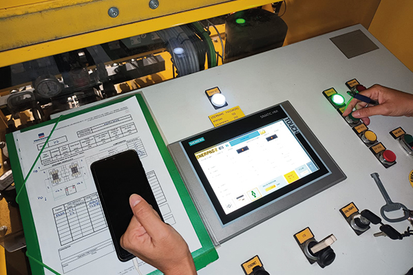
The computer-aided lifting system (Freyssinet)
To allow the placement of the new bearings, the deck was once again lifted with the jacks. Due to the higher height of the new bearings, it was necessary to cut the original plinths with a diamond wire. The lower plinths were then restored with self-levelling mortar. The new bearings were lifted onto the working area using the same frame and horizontal hoist as previously used in the removal of the old units.
The new bearings were installed with a thixotropic mortar on their upper plate. When the deck was lowered to its original position, it crushed the mortar thus ensuring proper contact with the new bearings. Once the mortar had reached the required strength, the jacks transferred the load to the new bearings. Lastly, the equipment was removed and the working area cleaned. Replacing the bearings of Pier One was simpler due to its location on land and easier access. The bearings of the three piers were replaced in six operations that each lasted under four hours. A topographical levelling measurement was conducted before and after each lift, taking approximately 45 minutes.
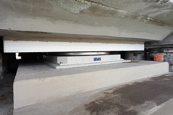
One of the new bearings in place (Freyssinet)
The project marks the first time Freyssinet has installed shear keys for a replacement operation. On lessons learned, Benito Gutierrez concludes “Probably the most important thing was the collaboration between the technical department and the site. This enabled execution without any major unexpected situations, as every complicated activity was studied jointly by the technical manager, the site manager and the foreman.”