The site of the Yamashiro Bridge scores highly in terms of dramatic views, but it is a contractor's nightmare when it comes to logistics. The bridge, which is currently under construction, is perched high up on the steep sides of a river valley with virtually no space for construction. The fast-flowing Dozan River far below is a popular spot for white water rafting.
Added to this, the bridge is in an area of outstanding natural beauty and therefore all construction activities have to be carried out with minimal impact on the environment.
The modest US$3.2 million single traffic lane bridge is being built to provide access to a local high school and has a span length of just 94m.
Because of the sensitive location of the bridge, client Yamashiro town council wanted the new bridge to be beautiful as well as offering good value for money.
Conventional arch bridges were initially considered as a possible solution to span the gorge, but there was simply nowhere to site the cranes needed to build them and it would have proved almost impossible to erect temporary falsework supports.
A more radical design was therefore proposed by designer Eight Consultants of Okayama and contractor Sumitomo-Mitsui Construction.
Their design is a composite steel and concrete inverted truss arch that uses a stressed ribbon to support all temporary works and construction loads. At the end of construction the stressed ribbon becomes the bottom chord of the final self-anchored truss arch bridge.
Although modest in terms of size - having an overall width of just 6.3m and a maximum structural depth of 10m - the bridge represents a technological first in Japan.
This is believed to be the first time in Japan that a stressed ribbon has been adopted to build a highway bridge. The method was previously used in 2002 to build Ganmon Bridge, however this was a pedestrian bridge with an even smaller span of just 37m.
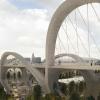
The distinctive steel diagonal truss members have been painted a bold orange for two reasons; firstly because the bright colour is thought to complement the vibrant colours in the surrounding forests during autumn and contrast with the greens of summer and secondly, because the bridge has very strong geometric lines a bold colour was thought to enhance and accentuate the shape.
According to Sumitomo-Mitsui Construction chief engineer Dr Akio Kasuga, Yamashiro Bridge is a very economical structure because temporary works are almost eliminated. "With the exception of the ground anchors at the abutments that resist the stressed ribbon loads, all of the structural members erected during construction form the permanent works of the final bridge. We have also designed the bridge to maximise the use of precast concrete and structural steelwork and minimise the amount of in situ concrete required," he says.
According to Kasuga, great care was also taken to ensure ease of construction by specifying that all structural components are small and light enough to be easily transported by standard road vehicles and erected by aerial ropeway.
The stressed ribbon cables provide all the support required for the construction of the arch, meaning that traditional falsework is unnecessary - obviously a huge advantage in such a tight construction site.
The procedure to build the bridge seems deceptively straightforward. To begin with, five external 63mm diameter cables were strung out across the valley and anchored to temporary anchorages on the rear of each of the two small abutments. The abutments were stabilised against high tensile loads imposed by the cables by ground anchors drilled into the valley walls. Precast panels were then placed on the external cables by an aerial travelling ropeway to form the stressed ribbon.
Panels are spaced 410mm apart to enable in situ concrete connecting stitches to be poured between them later. With all the precast panels installed, the ribbon acts as the lower chord member for the arch and carries all subsequent construction loads.
Every third panel along the ribbon incorporates a special panel that supports two pairs of 400mm diameter hollow steel tube diagonal members that will become the vertical truss diagonals of the final bridge.
Tubes have a maximum length of 9.6m, they were fabricated off site in pairs and transported to site by standard flat-bed trucks. Each pair of V-shaped units was then connected together into groups of four on site using a composite steel beam/in situ concrete joint before they were lifted into position by the aerial ropeway.
Each of the twelve groups of diagonals was temporarily braced together at deck level by steel H-beams for stability. However, these beams are also designed to act as tracks along which precast deck segments can be launched.
When Bd&e visited the site in September all diagonal members had been installed and erection of the precast deck segments was in full swing with the sixth segment being carefully launched out along the bridge.
A total of twelve, 5.9m long deck segments have to be installed, each one being positioned above one of the groups of four diagonals.
Once the deck segments are in their final position above the steel diagonals, in situ concrete will be poured to form a joint between the segments and the steelwork, which will create the composite truss structure. Next, 75mm thick precast panels will be laid along length of the deck and a 165mm thick in situ concrete slab will be poured on top.
Up to this point the stressed ribbon will have been supporting all the construction loads. However, once all the in situ concrete stitches between precast panels have been poured the five external cables are released from the temporary anchorages on the abutment walls and then connected to permanent anchorages on the large concrete diaphragm beams at each end of the bridge.
After the external cables are de-tensioned, the stressed ribbon will become the bottom tension member of the truss. This member will be further post-tensioned by six internal cables each comprising 12 15mm diameter strands which are inserted into ducts in the precast panels.
Once these internal tendons are stressed, the bottom chord acts as a simple beam and the bridge will finally behave like a self-anchored arch.
According to Kasuga, one problem encountered during construction has been the control of deflections. Because the bridge is so flexible because of all the gaps between precast members, deflections during construction are relatively large and difficult to control. Deflections are particularly noticeable when the stressed ribbon is de-tensioned.
"When the external tendons are de-tensioned we expect the bridge to sink by 20mm at midspan and then when the internal tendons are stressed the centre of the bridge will rise up by 40mm," explains Kasuga.
Interestingly, Kasuga explains that no prestressing is required in the deck slab because after de-tensioning of the external stressed ribbon cables, 70% of the remaining compressive stress will be distributed to the deck slab and 30% to the bottom chord.
Although this is the first tressed ribbon highway bridge to be built in Japan, Kasuga says this type of structure is ideally suited for the many span lengths of 80 to 100m commonly found in Japan's mountainous landscape.
"We believe that there are many future opportunities to adopt this design for highway bridges. Provided the span length is kept within about 110m and the width is in the range 10-15m, the design concept works because all structural components