All photos copyright Michael Zimmermann
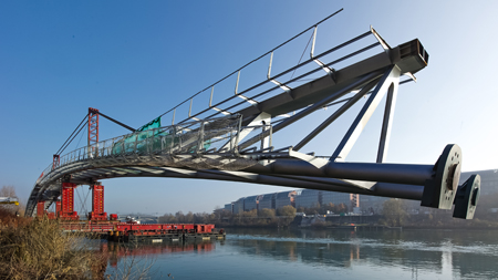
A temporary cable-stay system had to be used to enable a footbridge to be installed as a single piece over the Rhone River
A new footbridge in Lyon, France, is set for completion this month after a complex installation operation which took place at the end of last year. The Passerelle de la Paix was designed by Schlaich Bergermann & Partner and Dietmar Feichtinger Architects, winners of a design competition that was held in 2009, and was floated into place during a complex procedure last November.
The US$20 million bridge will link district six in Lyon to the Park of Saint Clair at Caluire et Cuire, as well as to the Renzo Piano-designed Cité International congress hall and entertainment complex. The bridge itself is steel structure designed to cross the Rhône River in a single span; it is 220m long in total, with a main span of 160m and a 60m-long approach bridge on the park side of the bridge.At the midspan the deck is 8m above the water.
The structure consists of two arches formed of tube sections, which create the bottom chord, and a box-girder which creates the top chord; top and bottom chords are linked and stiffened by triangular steel elements and diagonals to create a truss structure. The elements of the three truss girders change their relative positions across the length of the bridge.
As well as offering a direct connection between the main routes on each side of the river, the bridge deck can also be reached from the river banks via stairways which are fixed to the outer arch by cantilever elements. The structure itself works as a combined arch-cantilever, with the deck girder fixed monolithically at the abutments.
A secondary structure consisting of transverse and longitudinal beams provides the substructure of the light, wooden deck. The main deck of the bridge is 5m wide with a 1.5m-wide stairway; at the midspan of the bridge, the deck is 8m wide. The steel superstructure uses S355 grade steel, while the wooden deck is made of oak planks of 50mm thickness.
In order to transfer the loads effectively, soil diaphragm walls were used to create an efficient foundation. Assembly and installation of the bridge was carried out in three main stages, the first of which involved the construction of the diaphragm walls for the foundations, which are 10m by 14m in plan, and 20m deep.

At the same time, the steel elements for the superstructure were fabricated in Aigle in Switzerland where steel manufacturer Z&M is based. The heavy-load truck transport was organised in three phases. The two ends of the main arch were assembled and welded on the site, after the single tube elements up to 16m long, diagonals and vertical diaphragm structures and upper box girder units were brought to the site by truck. The central third of the arch was brought to site in a single piece.
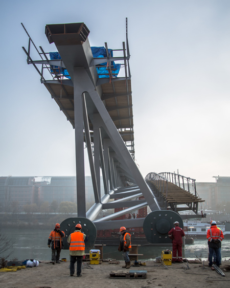
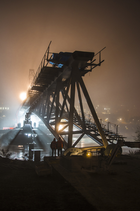
These three sections were assembled on site to a super-elevated geometry on temporary supports, with the truss-arch structure being welded and the coating completed. Assembly took place on one side of the River Rhone, next to the permanent alignment of the crossing. The second main phase began with the installation of the temporary cable support system on top of the bridge structure.
High performance jacks were used to lift the steel structure onto two Mammoet temporary supports, each consisting of two towers, and they moved the structure along a temporary rail system that had been built. The jacks were able to raise the structure about 2m higher than its final elevation; they had a capacity of about 500t per column, well above the 200t that was required.
The purpose of the temporary rails was to provide a route along which the bridge could be moved, using Teflon supports, and manoeuvred onto the barge. Once the bridge was on the barge, it was turned to the permanent alignment and the bridge structure was lowered into its final position. The arch bearing points were adjusted using shim plates, and prestressing was installed.
The third phase involved the installation of the upper chord box girder, as well as the damping system and other equipment. The damping system was subjected to dynamic testing at this stage. This specific construction sequence was proposed by the steel subcontractor and its structural engineer as having a number of benefits.
It was intended to minimise the time for which the river had to be closed to shipping traffic, and also offered the best solution for achieving geometrical accuracy during assembly on the site. Another benefit was that welding and coating operations were simplified with this procedure, and installation of equipment was made easier.
Safer and more comfortable working conditions for staff were another consideration, with time working over water minimised. But the construction method also raised challenges for the contractor, in particular the difficulty of carrying out a heavy lifting operation that demands constant monitoring of the forces in the jacks and control of the deflections experienced by the cantilever structure.
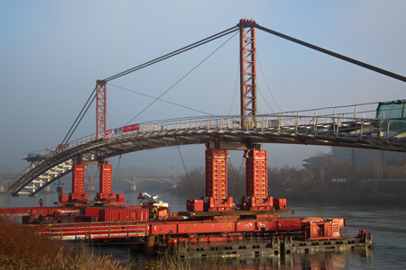
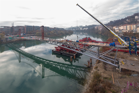
The entire structure to be moved was 160m long and 8m tall and the operation involved translating this structure horizontally by 30m on rails and onto two 60m-long barges which were coupled side by side, and on which temporary rails had been installed.
Moving such a long, flexible and asymmetrical structure required careful planning and complex temporary works.
One significant part of the temporary works was the cable support system that was installed on top of the structure. Two temporary steel towers were erected and cables were connected to the deck, forming a 56m-long cantilever at each end.
Appropriate forces induced in the cables by the use of jacks were required to counterbalance any vertical deformation of the cantilever structure. The whole procedure required very precise movement of unusually heavy, large elements.
As well as the challenge of moving such an unusual structure, the contractor had to take account of the different stiffnesses under the supports – the soil stiffness was different from that of barge – and the barge displacement had to be very precisely controlled and adjusted during the operation.
Once the bridge structure was secured on the barge, the vessel was floated into position, a process involving a major turning operation, and once in position, the bridge structure was lowered onto the axes of the abutment points.
The jacks on the towers and those controlling the cable support structure had to be adjusted with great precision, and the tolerance for inserting the tension bars into the anchor points was very small. Before the lifting and floating operation could begin, certain conditions had to be satisfied – the water level and current of the River Rhone had to be within specified limits, and the wind speed had to be below 60km/h.
#Accelerated construction
#Arch
#Construction
#Lifting & launching
#Footbridge
#France
