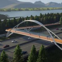

Peter Vygodin reports on a dramatic new bridge that is proposed for the Neva Bay in St Petersburg
Authorities in the Russian sea port of St Petersburg are planning construction of a new landmark bridge to provide a route across the Neva River delta for the Western High Speed Diameter Ring Road, which is an express motorway. Tenders for the privately-financed design and construction of the project are currently being invited, with site work expected to start some time next year.
The route layout and elevation profile of the new motorway offer an opportunity for engineers to design a large-scale, modern transportation structure that not only links the banks of the Neva but also adds a new architectural element to the panorama of the city.
Several other new buildings and developments on the St Petersburg seafront will contribute to the creation of a new view of the city from the Gulf of Finland - including a new sea terminal and surrounding buildings on reclaimed land on Vasilievsky Island. While the new terminal and the proposed high-rise buildings will form the focal point of the seafront, the bridges of the new motorway will be a kind of 'Ariadne's thread' that will create a link between this focal point and its surrounding areas. It will connect the northern and southern shores of the Neva Bay and link the sea and the city to form a single, integrated space.
The seaport's two main navigation channels run one each side of Vasilievsky Island: Petrovsky Channel on the north side and Korabelny Channel on the south. These channels will be crossed by new bridges which have to rise some 40m above water level to provide sufficient shipping clearance. At the initial design stage of the Korabelny crossing, an architectural study of 15 different types of bridges was carried out, including cable-stayed, arch, suspension, extradosed and box girder solutions. The development of the design for the new bridge was carried out by ZAO Institute Strojproect. The client and the city's committee for urban development and architecture selected the cable-stayed option with a 320m-long central span and two 125m-high inclined towers. The form of the bridge has a certain likeness to a drawbridge.
This similarity is no accident; drawbridges are one of the most famous and beautiful symbols of St Petersburg. By implementing the proposed design, not only will the appearance of the waterway be improved, but it will balance out some of the more unappealing structures and improve the view of the city from the water, engineers believe. In particular, it is intended to make the skyline more regular, shifting the unappealing port and treatment facilities to the background and framing the Korabelny Channel with beautiful structures.
The proposed bridge will carry eight lanes of vehicular traffic: four in each direction with a barrier in between. Each carriageway will be 16.5m wide; the width of the structure between cable-stay planes will be 39.5m and its total width including the aerodynamic cornices is designed as 47.3m.
The total length of the bridge superstructure is 620m and bearings at the bridge towers are designed to accommodate the horizontal load only - vertical loads are completely accommodated by the cable-stay system. The superstructure rests on two bearings at the abutments, one of which is multi-directional, the other uni-directional. Both braking loads and wind loads acting longitudinally on the structure will be resisted by dampers installed at the towers. The main span of the bridge is set at 320m while the distance between the towers and the abutments will be 150m on each side.
The superstructure cross-section consists of two main box girders connected by H-shaped transverse beams, spaced at 3m centres. The outside edge of each main girder has cornice-deflectors whose design was fine-tuned through aerodynamic analysis and wind-tunnel tests.
Because of the width of the bridge, the transverse beams are made up of three units of variable depth: ranging from 2.4m to 3.2m deep and in length from 11m to 13m. To facilitate the arrangement of joints between the precast and the cast in situ reinforced concrete slab, five longitudinal H-beams with a depth of 420mm and spacing of 6m are placed between the transverse beams. The three central longitudinal beams are connected to one another and to the transverse beams by longitudinal counter-bracing consisting of pipes of 140mm diameter with 8mm-thick walls to ensure that the main beams and the beam grid superstructure retains its shape during erection.
The main beams are designed with a box-shaped cross-section and overall dimensions of 1.4m by 2.4m. The thickness of the lower chord steel ranges from 25mm to 60mm while the upper chords vary from 20mm to 32mm, and the webs are 20mm thick.
The upper and lower chords of the transverse beams have a constant cross-section of chord 650mm by 32mm while the web of the cross-beams has a height that varies from 2.4m at the junction with the main beam up to 3.2m along the bridge axis. Flexible rod arresters with diameter of 22mm are welded to the upper chords of the longitudinal and cross-beams, to ensure their connection with the reinforced concrete carriageway slab.
The carriageway slab consist of both precast and cast in situ reinforced concrete. The slab is 200mm deep across the main span of the superstructure and 300mm deep over a 126m length at the tower and is formed of precast slabs measuring 2.6m by 5.4m. The joints which are 360mm and 560mm wide are located above the chords of longitudinal and cross-beams with widths of 360mm and 560mm respectively.
The tie-in segment of the slab at mid-span will be made of cast in situ concrete; permanent steel formwork has to be used in order to prevent tensile stresses being created in the concrete.
Under some live loading cases, the abutments will experience uplift, hence the designers have had to take this into account by incorporating a counterweight of 600t in the form of a cast in situ reinforced concrete diaphragm located between the end and the transverse beams.
Despite its width, the superstructure is suspended from just two planes of cable stays. The cable stay plane of each half-span consists of 26 stays spaced at 12m centres corresponding to the length of the main erection units of the main beams.
Tensioning of cable stays will be carried out from the side of the carriageway and Freyssinet's anchor system will be used for attaching the cable stays, both fixed and movable. The anchor used for the towers will be fixed while those used at the deck will be movable. The design also includes cable stays consisting of high strength wire (strength class 1860N/mm2) and made up of 55 to 91 strands.
To prevent mechanical damage to the lower anchorage zones and the protection sheath the cable stays will be provided with anti-vandal steel pipes that are long enough to ensure the distance between the footpath and the top of the steel pipe is at least 2.5m.
Under the superstructure there is provision for inspection facilities to enable visual inspection and service of the deck and the anchorages of the cable stays.
The inclined, reinforced concrete towers are 125m high and are inclined at an angle of 15o from the vertical. At carriageway level, this inclination is created by means of the reduced cross-section, hence the front surface is almost vertical. The lower cross-section is 19m by 6.5m with the rear and front walls having a thickness of 2m and 0.8m for the side walls. Above the carriageway the tower is slightly tapered at the top with a cross-section of 6m by 4.1m. The thickness of the walls varies very little, and only decreases within the cable-stay an