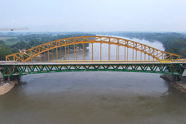
The New Boca del Cerro Bridge takes shape above the Usumacinta River Canyon
Spanning the fastest flowing river in the country, the New Boca del Cerro Bridge (‘Mouth of the Mountain’) is the most emblematic structure of Section 1 of the Tren Maya, one of the most significant railway projects currently under way in Mexico. When complete, the over 1,500km-long Tren Maya (‘Mayan Train’) railway will traverse the Yucatán Peninsula via two rail routes, starting at Cancún International Airport and connecting traditional Caribbean tourist hotspots with lesser visited areas inland.
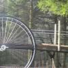
The new bridge is located in an officially protected area at the end of the Usumacinta River Canyon, 6km from the town of Tenosique in the state of Tabasco, next to an existing 1950-built arch bridge. The existing historical structure carries extraordinary cultural value and represents an engineering milestone of its time.
The arch crossing is around 189m long with a 150m-long main steel span: it was designed to accommodate road traffic and a railway line (currently out of service), as well as pedestrians via a small pavement. The steel structure consists of parallel arches located above and at either side of the deck. Each arch is composed of two main chords at different heights that are joined together by a Pratt truss. The entire steel structure of the bridge was assembled with riveted joints.
The original construction method used for the historical bridge served as the inspiration for that of the recently completed new bridge. The existing bridge was built using cantilevered construction of the arch’s truss from the sides of the river, where the steel structure had been temporarily embedded by extending the upper chords of the two arches. The arch trusses were assembled using gantries that moved over the arch, and which were supplied with the required materials by barges beneath. This allowed elements to be lifted vertically and then assembled in their final position. This way, the structure advanced symmetrically from each bank until arch closure in the centre. Finally, the embedded sections at the sides were removed, the vertical hangers mounted and the deck structure hung, again with the barges supplying necessary parts.
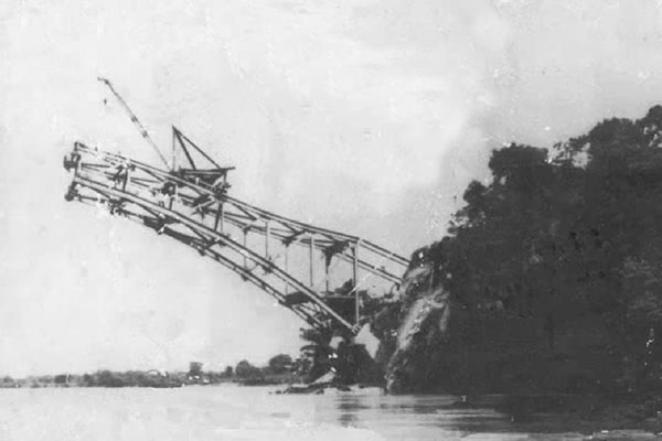
Construction of the cantilevered arch truss while temporarily embedded in the embankment
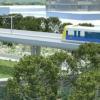
Having considered the particularly beautiful scenic setting that is further enhanced by the existing bridge, the new structure was designed to be as invisible as possible. It is therefore placed in parallel, at a similar deck elevation, with a truss layout that mirrors the configuration of the original structure, and also painted green to blend in with the natural environment. As a result of these design factors, when viewed from downstream – which is the typical viewpoint – the two bridges appear as one.
The selection of the structural typology was also strongly conditioned by the advantages offered by the construction method under consideration, which as mentioned was similar to that used on the existing arch bridge.
The central span was erected by incremental cantilevers from both side spans, thus making the construction independent of the river and its hydrological conditions, a crucial aspect considering the great variability of the river water level. Moreover, the construction process did not require the installation of a launching yard or other auxiliary facilities such as tie-up towers: the area occupied on the banks of the river around the abutments was minimal, which lessened the volumes and excavation slopes as well as the impact on the protected areas around the bridge. Finally, placing assembly yards in the surroundings of the abutments reduced the distances travelled by the segments to their final position.
The central span was designed as a truss with double composite action: a top concrete slab, two steel truss planes and a bottom concrete slab at the sides next to the piers. The upper steel chord layout is mainly horizontal while the lower cord has a parabolic layout. The total depth varies from 6.3m in the centre of the span to 11.4m over the piers. These values provide a ratio of L/25.39 and L/13.91 respectively, suitable for a railway bridge.
The truss is composed of two vertical planes separated 4.5m between axes. Both upper and lower chords are designed as box sections with 0.8m sides. The top plate of the upper chord is wider (1.1m) to allow the correct support of the upper precast slabs. The same applies to the bottom plate of the lower chord which, in this case, only extends inwards. This allows the arrangement of bottom precast slabs or Tramex-type gratings, making the deck accessible inside for future maintenance and inspection of the bridge.
In hogging areas, the lower precast slabs allow the casting of a bottom slab, which is connected to the steel structure. The bottom slab starts at 46.25m from the pier axis. Minimum thickness of the bottom slab is 0.3m, increasing to 0.7m in the section where it connects with the concrete structure.
The Warren-type truss uses only diagonal elements and is very efficient, as it reduces the number of chord connections by half when compared to the Pratt-type truss. Although the Warren-type truss requires the compression diagonals to have a somewhat larger area, since the number of elements is reduced by half and the design is fatigue-conditioned (being a railway bridge), its use reduces the overall amount of steel required.
Regarding the distribution of the diagonals, truss nodes were arranged every 7.5m in both upper and lower chords to match the configuration of the existing Boca del Cerro Bridge. The nodes start 5m away from the pier axis in the upper chord and 8.75m in the lower chord. Diagonals are 0.6 by 0.8m rectangular box sections, and the connection between diagonals and upper and lower chords is made by a web-butt weld and by extending the flanges inside the node, which made the connection very simple. The principal elements of the truss (diagonals and upper and lower chords) are made of Gr50 steel plates (Fy=345MPa).
The advantage of the composite steel-concrete solution of the central span is the reduction of its self-weight, which allows it to be balanced by the short concrete lateral spans. The lightness reduces the length of those spans to 0.1875 times the central span.
The lateral prestressed concrete spans present as box girder sections with outer perimeters similar to those of the composite truss. At the end supports, the deck is vertically anchored to the abutments to prevent it from being lifted off in the worst case scenario. This way, the pull produced on the abutments is compensated in a very efficient way by the self-weight of the buried elements and the earth located on the footings.
Due to the proximity of the columns of the new bridge to the ones of the existing bridge, it was necessary to pay special attention to the foundations during design. To this end, it was considered that the best solution was to use shallow foundations with the lowest elevation at the same level as those of the existing structure, in order to avoid any impact to the existing structure. Due to the proximity of the foundations to the slope, it was necessary to improve soil characteristics to obtain sufficient capacity in the rock mass to accommodate the loads transmitted by the foundations.
Bridge construction began in April 2022 with the erection of the abutments and piers. Lateral prestressed concrete spans were constructed by means of falsework, a phase during which the starting steel elements of the truss were embedded in the concrete. Meanwhile, steel segments of truss were assembled in yards near the abutments.
The lateral spans were fixed longitudinally to the abutments by means of longitudinal prestressed anchorage bars. At abutment C-1, the fixed point was permanent while, at abutment C-4, the point was designed to be temporary until closure of the central span.
Once the lateral concrete spans had been completed, erection of the steel truss continued by cantilevered construction from each side, using specially designed moveable lifting frames. Segments were delivered to the lifting frames at the pier positions by a trolley from the assembly yards. Afterwards, the moveable lifting frames transported the segments over the truss to their final position.
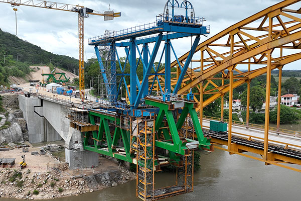
Segment installation with the moveable lifting frame
The typical work cycle involved picking up a segment at the rear end of the moveable lifting frame; centering the segment within the frame; the frame advancing to the front of the cantilever; moving the segment forward within the frame and, finally, lowering it down to its final position. The process continued, segment by segment, until the steel truss was closed at midspan.
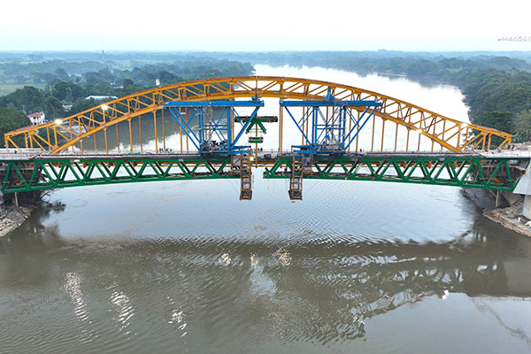
The bridge nearing closure at midspan
After completion of the steel truss, the second phase of the concrete lateral spans prestress was carried out as well as the casting of the lower concrete slab. Prefabricated slabs were then placed on the truss and the top concrete slab poured. The installation of ballast, track and other finishing elements followed on the deck.
In order to handle, manufacture and ship the 1,100t of steel elements to the working site, the truss had to be divided into simple elements, which consisted of upper nodes, upper chords, lower nodes, lower chords, diagonals, horizontal struts and cross bracings.
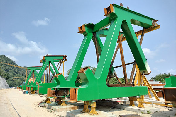
The truss was divided into simple elements to faciliate fabrication and transport
The individual node and chord elements of each module were assembled in the workshop to reduce the number of joints on site and facilitate shipping. Later, each plane of the truss was connected in a horizontal position on site and, subsequently, both planes oriented vertically and joined together by means of horizontal bracings, prior to lifting.
The complexity of the steel structure required significant preliminary work, as did the development of a series of repetitive details for the assembly drawings. The workshop drawings resolved all the joints, welds, transitions and specific details, and avoided future execution problems. This effort was especially necessary in this project because, as a railway bridge, structural steel fatigue was an important design factor. For this reason, it was necessary to pay close attention to joint details, such as smooth transitions of dimensions and thicknesses, circular and tangent finishing of plates, flush grinding at weld ends, etc.
The Boca del Cerro Bridge was completed in December 2023, as was the 228km-long Section 1 of the Tren Maya. The Tren Maya is expected to open in its entirety by the end of February 2024.
Miguel Ortega Cornejo is managing director of TY Lin, Madrid, Spain and associate professor at the Civil Engineering School of the Technical University of Madrid. Pedro Atanasio Utrilla and Jokin Ugarte González are senior project managers, TY Lin, Madrid, and Kevin Rincón Crespo is a structural engineer at the same firm.
New Boca del Cerro Bridge
Client: Fonatur
Contractor: Lamat Consorcio Tramo 1
Detailed design and project management: TY Lin
Steel fabrication: Recal
Heavy lifting: VSL