
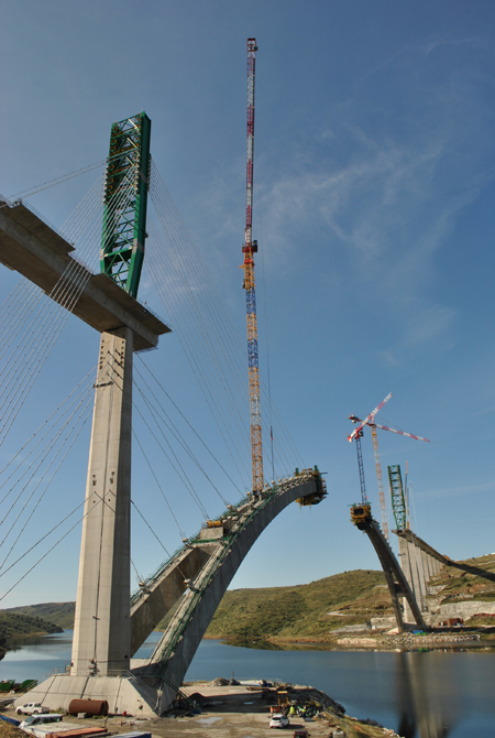
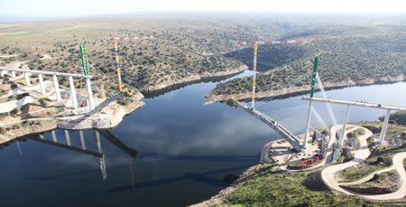
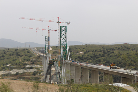
With its two cantilevers set to meet in the middle of the 384m-long arch span in September, the world’s third longest concrete arch – and the world’s longest for high-speed rail – is on track for completion. The Almonte Viaduct is 996m long in total, and its central arch span will carry high-speed trains over the Almonte River at the point where it flows into the Alcantara Reservoir in Caceres, some 340km south-west of Madrid.
The bridge is being built for the state-owned Spanish railway infrastructure administrator Adif, which reports to the Ministry of Development, and it is part of a larger US$110 million project that encompasses three other now-completed bridges on a 6.3km-long route of double high-speed track in Garrovillas de Alconetar near Caceres.
The initial intention was that the high-speed rail project would connect the Spanish capital with Lisbon in Portugal, but the financial crisis prevented the network from extending across the border and the current plan is for the link to terminate at Badajoz.
The design of the viaduct has been carried out by Arenas & Asociados and Idom (Bd&e no 72), and the main contractor is a joint venture of FCC Construccion and Conduril, with FCC Technical Services providing detailed design and construction process design works.
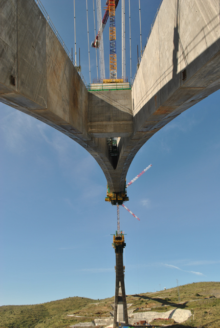
The arch consists of four slender legs with hexagonal cross-sections that rise from the foundations – two at each end – and taper gradually until they meet and form a single octagonal leg over the central section. The 384m-long arch will carry eight piers while an additional 14 piers support the viaduct approaches.
Only the Wanxian Bridge in China with its span of 420m and the 390m-long Krk I Bridge in Croatia have longer concrete arch spans – and these have single legs as opposed to the double-leg design that characterises many of Arenas & Asociados’ larger bridges.
The concrete elements of the arch bridge are being built using travelling formwork, with each segment anchored back via a cable-stay system to a retaining foundation, either through temporary steel towers or through intermediate piers. Variability in river depth resulting from nearby hydroelectric activity precluded the use of boats to lift prefabricated concrete sections from the river.
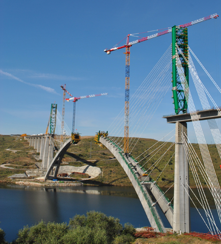
The original design of the arch called for individual elements 3.5m to 4m long, but this was revised by FCC Technical Services to 6.5m long, in order to simplify the construction process, as project manager Pedro Cavero explains: “By increasing the length of each element we reduced the number of elements required for each leg from 52 to 32, which also reduced the number of times the climbing formwork traveller went forward. This minimised the number of operations thereby reducing the risk associated with the process.”
One of the early hurdles faced at pre-construction planning revolved around how the two legs that rise in parallel on each side of the arch would join together, 90m from land and 45m above the river. Each leg has an hexagonal cross-section starting with a 6.9m depth and 3.7m width, gradually increasing in width until the legs join to form a single octagonal cross-section with a 4.8m depth and a 6m width at the crown of the arch.
In 2010 FCC met with ten formwork traveller design companies to discuss possible solutions, recalls Cavero: “Only one company – the Spanish firm Rubrica Ingeniería – was able to come up with a potential solution”. The solution involved two climbing formwork travellers working independently, one on each leg, with one going ahead of the other at the tip of the cantilever. The exterior section of the leading traveller would then be removed to make space for the following traveller to move forward and aside. The two would then be connected to create a single traveller that could be used to form the single structure across the middle of the arch.
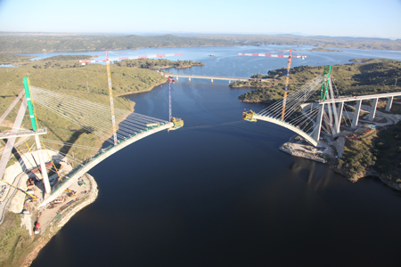
Further alterations to the proposed traveller design were made by FCC Technical Services in order to optimise the construction process, explains detailed design manager David Arribas: “The length of the upper part of the traveller had to be reduced in order to shorten the distance between the forward cable stay and the new forward concrete element, otherwise the tensile stresses in the concrete wouldn’t have met the design requirements.”
In order to cope with the compression stresses in the arch, the segments are constructed using 80MPa self-compacting concrete which was specially developed for this project and has since been patented by FCC subsidiary Cementos Portland Valderrivas. Ultraval SR concrete reaches 40MPa in 12 hours and 90MPa in 28 days, and it was mixed with fly ash and river sand as well as admixture Glenium TC1425.
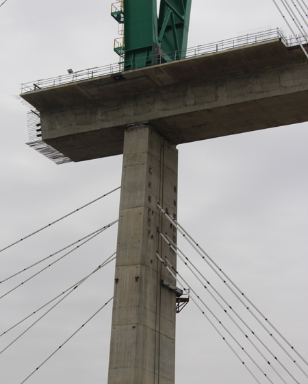
Another significant challenge was the design and erection of a 54m-tall, 500t temporary steel tower that was needed to guide the temporary cable stays from the leading elements of the arch to the anchors at the piers. The innovation here, explains Cavero, came in the form of the choice of support on the deck. “The main difference between this and other towers is that instead of constructing a fixed connection, we made it pinned. The idea was to separate the structural behaviour of the steel tower from all the other effects such as arch cantilever movement and thermal effect on the cable stays. By having an articulated support, we could keep these forces separate from those of the rest of the structure, which would not have been possible with a fixed support.”
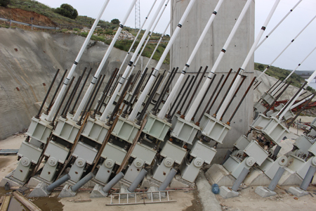
“Moreover,” adds Arribas, “using a pinned support opened up the possibility of raising the steel tower into place as a whole unit from a horizontal position rather than using a crane to build it up section by section. This way we were able to construct a steel tower with only two tower section joints, as opposed to seven had we used a crane.” Hence the steel tower could be erected quickly in just 22 hours.
The bridge deck is 3.1m by 6m box girder made of post-tensioned concrete. Each 45m stage of the deck is cast in place using an overhead travelling gantry – which was not part of the original plan, as slots visible in the supporting piers demonstrate. “Unfortunately the company we were going to use went into liquidation so we couldn’t use their underslung travelling gantry. Fortunately we came across this one,” says Cavero, adding that it was acquired from Portuguese company AP Bridge Construction Systems.
Of note are the superstructure’s abutment foundations, which are 15m in length in order to accommodate the entirety of the high-speed rail track’s expansion device. In the past, explains Arribas, these devices would be laid partly over the concrete abutment foundations and the terrain, with a connecting wedge made of a mixture of aggregate and cement that assists the transition between the hard concrete and the softer earth. “Although conceptually this should work, we are seeing a number of high-speed rail projects requiring the concrete foundations to cover the entire length of the expansion devices to avoid potential ground settlement which could affect the sensitive devices,” says Arribas.
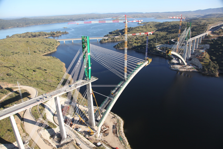
Due to the fact that the bridge’s fixed point is at the centre of the arch, where it is rigidly connected to the deck, both abutments are expansion joints. “However,” says Arribas, “because the deck is being constructed from the sides over Teflon supports – and is therefore longitudinally free, we placed provisional anchor points at each abutment. As deck construction has progressed we have moved these fixed points to temporary steel structures at each of the access piers of the arch.”
To increase productivity and reduce work at height the viaduct access piers have been built using climbing formwork with prefabricated reinforcement cages placed in situ by crane. Each lift is 5.5m long, with the cross-section varying from 10m by 4.5m to 6m by 2.4m at the top.
Four of the foundations for the viaduct access piers also accommodate retaining anchors for the temporary cable stays that support the arch cantilevers. The retaining anchors, the number of cable stays and the size of pedestal all had to be redesigned when it was agreed to increase the length of the arch elements to 6.5m.
Cavero explains that because the rock underneath the foundations consists primarily of slate, there was a possibility of some movement once the pier foundations had been poured - even with the 66 retaining anchors of 16m root length per pier. As a result, a total of 2.8km of additional holes were drilled and 274t of grout injected to provide additional support for the piers.
The retaining foundations themselves were formed using 3,600m3 of 30MPa concrete and 632,102kg of reinforcement, with 832 Macalloy bars per pedestal.
But the quantities of concrete and reinforcement in the pier foundations were dwarfed by those used for the arch foundations, which required a total 7.6km of holes injected with 255t of grout. As for the foundations themselves, Cavero explains: “It wasn’t possible to pour 7,500m3 of concrete in a day for reasons of logistics as well as the potentially damaging effects of the high temperatures created by the curing process. We split up the process into different phases looking for volumes of around 1,000m3, which is what we could handle in a day with the local resources available.” He likens the size of each arch abutment to building a seven-storey car park 20m underground.
Arch piers six and 15 had to be constructed differently to the viaduct access piers because the temporary cables supporting the first 13 elements of each cantilever go through these piers and down into the stay cable anchors. To accurately guide the cable stays to their anchors, units composed of criss-crossing metal tubes were assembled and placed in a dedicated recess inside the piers. “Due to the forces transmitted by the cable stays to the pier we built the sections holding the metal sleeves in solid concrete,” explains Arribas, adding: “It was a geometric challenge ensuring that the direction of each tube was precisely aligned with the position of each cable stay.”
Between now and final completion in June 2016, two more cranes will be placed on the cantilevers and the arch will be closed, after which the cable stays and steel towers will be removed. Construction of the arch piers and deck will be carried out, and once complete, it will be fixed to the arch to achieve its permanent structural scheme.
Reviewing the work so far, Arribas and Cavero highlight a number of innovations for Adif and FCC including the aerodynamic study carried out by the University of Western Ontario, Canada to analyse the aerolasticity effects on the bridge, the development of the 80MPa concrete, the design of the formwork traveller itself, and the sensors that were installed on the bridge which are used to compare theoretical and live conditions, enabling the construction team to make corrective changes to the cable stays and the setting out of segments according to varying ambient conditions.
With the ongoing expansion of the high-speed rail system in Spain, Cavero and his colleague Arribas believe that the Almonte Bridge will position Spain as a leader in this type of construction. Considering that only a few kilometres away another remarkable concrete arch bridge is being built over the River Tajo, this time with a 324m span, it is quite likely that they will be proved right.