In 2018, the City of Paris launched a competition for the relandscaping of parks and gardens between Place du Trocadero on the right bank of the Seine and, on the other side, the Eiffel Tower, Champ de Mars gardens and the École Militaire. Connecting these two spaces will be a new 25m-wide tree-lined avenue created on the historical Pont d’Iéna, or Jena Bridge.
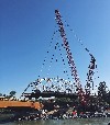
 Competition proposal for Jena Bridge (MIR)
The winning project by Group One, led by the landscape architect Kathryn Gustafson, went beyond simple pedestrianisation, instead aiming to transform the bridge into an integral part of the landscape whilst providing continuity across the river banks with references to the elegance of the Haussmann Boulevard.
The design team was deeply aware that a close examination of the existing bridge and its history was needed, given that a number of interventions had been carried out over the years. Careful review of the effects of the proposed modifications, in addition to a thorough understanding of masonry bridge design, were crucial.
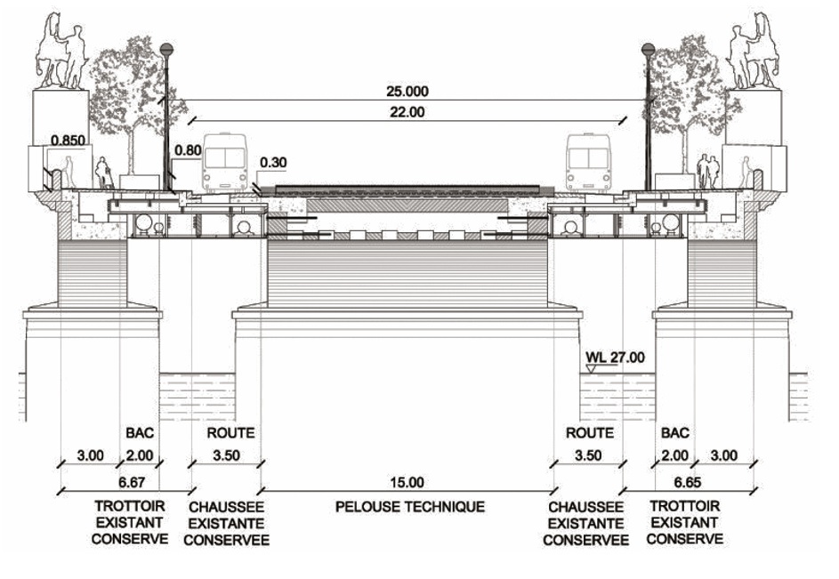
Constructed between 1808 and 1816 at the behest of Napoleon 1st, Jena Bridge is 152.2m long and consists of five masonry arches of 28m spans. It was built from Saillancourt stone with a mortar joint of minimal width. The rise of the stone arches measures 3.4m, thickness at the spring is 21m, thickness at the crown 1.43m and the depth is 14m. The four stone piers and two abutments are founded on wooden piles.
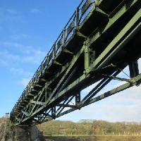
There have been a number of interventions on the bridge since it opened over 225 years ago, the most significant having taken place for the 1937 Exposition Internationale, when it was permanently widened from 14m to 37m using concrete arches and foundations on either side of the arch bridge, to which it is linked by steel purlins. Also relevant was the introduction of motorised traffic on the widened bridge, which increased loads on the original section by approximately 35% and led to controlled access for heavy vehicles.
 Proposed planted promenade (Gustafson Porter + Bowman)
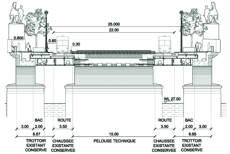
In this historical context, the principal concept of the design is the transformation of the road bridge into a tree-lined green space with a central lawn, which is as wide as possible and aligns with the Eiffel Tower. The design integrates two lanes suitable for restricted use by buses, bicycles and security vehicles (with potential for later repurposing for normal traffic) as well as vehicular safety restraints and lighting.
Since landscaping would alter the loads and change the ratio between the live and permanent loads, it was necessary to determine the bearing capacity of the vaults and foundations.
As the available load bearing capacity of the bridge would define the landscape project, a yield design analysis was carried out following the recommendations for stone arch bridges outlined by SETRA, the national technical department for roads and engineered structures.
We noted three approaches available to determine the allowable stone strength and – consequently – the bridge’s load capacity. These are Eurocode 6; CIB’s International recommendations for masonry structures; and the rules of the ‘elders’[5].
SETRA guidelines refer to CIB values for stone strength, which are higher than those from Eurocode 6. They are derived from masonry rather than bridge theory and are conservative. SETRA guidelines refer also to the historical and proven method of using 1/10 of the characteristic strength of the stone as allowable strength. In addition, this value must be used for self-weight calculation without an additional safety factor, as was the common practice of the time, when ultimate calculations were not yet established.
Site investigations gave a compressive strength of 26MPa for Saillancourt stone, which enabled the definition of allowable compressive strength for the masonry (stone and mortar) according to the three methods: 2.6MPa according to 19th century rules, 6.7MPa by CIB, and 2.37 with Eurocode 6. Calculations were subsequently based on a simple compressive strength of 6.7MPa.
The calculations which had been used originally for the widening of Jena Bridge were carried out using Méry’s method[1], a now-obsolete theory developed in 1840 that can no longer be used in the assessment of a bridge’s stability and maximum load capacity. In the first approach, we recalculated the bridge with the Méry method, finding the same results as in 1934.
To know the potentially bearable load of a masonry structure, yield design theory as developed by Jean Salençon[2] is a simple and effective method which avoids dealing with the constitutive relation of the masonry. Yield design theory has been applied to masonry architecture by Heymann[4] and, subsequently, to masonry bridges, especially in France using SETRA guidelines[5]. Here, solutions are characterised by an infinity of thrust lines that are used to identify a so-called optimal thrust line which best satisfies criteria around compressive strength, friction[3] and rupture factor. The yield design is a static exterior approach since it seeks the loadings for which the vault is unstable. Thus it is possible to define a rupture factor (k) for the optimal thrusts line, defined by the ratio of the extreme loading on the applied loading (k = FM/F). Theoretically, if the ratio is less than one, the structure is certainly unstable. If it is greater than one, it is only potentially stable. The recommended value, to be in a safe domain, is at least three. Below this value, a further analysis is necessary to confirm the stability of the structure.
On Jena Bridge, it was assumed that the self-weight of the stone was 2.3t/m3, according to recent investigations.
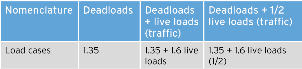
Due to the age of the structure, we used the Fascicule 61 Titre II [6] in order to define traffic live loads for the uniform traffic loads assumptions, as well as the BAEL [5] (Concrete) for the load combinations.
The calculations showed that the maximum bending moments were logically at the births of the vault. Although not null, the value of the bending moments at the key was relatively close to zero, which may imply a very low eccentricity of the optimum thrusts line at this location. We also could see a shift of the bending moments when only half-loads were applied.
We noted the symmetry of the normal forces in the body of the arch for all load cases. The value of normal forces increased by 33% only for deadloads, due to the enlargement of 1937. The value close to zero of the eccentricity at the keystone confirmed the hypothesis induced by the low bending moment at this location, ultimately due to a central position close to the neutral axis of the optimum thrusts line. The curvature allows most of the key stresses to pass through the normal forces. The eccentricity was greater in the rest of the body of the vault, also confirming the figure of the bending moments.
It is important to note that the eccentricity remained less than a third of the segment height over the entire length of the arch, oscillating between 22% above the neutral axis on the extrados side, and 8% below on the intrados side. We concluded that the line of optimal pressures never leaves the central third of the vault for both the original vault and the one overloaded with the extension of 1937, thus justifying the static equilibrium of the structure from a geometrical factor point of view. The thrust lines for the different load cases corresponded to the lines of optimum pressure, within the admissible range for each load case, best satisfying the criteria of zero tension in the masonry, no sliding, and finite compressive strength estimated at 6.7Mpa.
The resulting values of the rupture factors are summarised here:
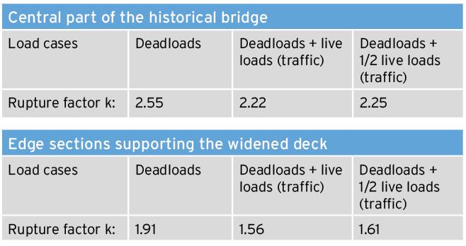 Results of the rupture factors according to loadcases for both parts of the masonry vault
Under permanent load, the rupture factor in the central part was certainly less than 3, but greater than 2.5 which may be acceptable given the fairly central position of the optimal thrust line in the body of the vault under this combination. Under traffic loads, the rupture factor was less than 2.5, which becomes critical. Nevertheless, it is necessary to emphasise that the live loads used here is a rare case of live loads and not a frequent situation. Moreover, the calculation remains very sensitive to geometric variations and to the values of resistance to compression. The hypotheses taken here are the most unfavourable, but they exist.
The edges of the arch which had served as supports for the 1937 extensions were the most problematic. As the value of the fracture coefficient is less than 2 for all combinations, it does not meet SETRA acceptability criteria, even if we can consider that the arch obviously remains theoretically stable. The uncertainty of the assumptions makes the value close to a value of 1, which contradicts the fact that the arch is in service and showing no pathology. The findings show that there is currently no safety margin and no more residual bearing capacity, suggesting that the bridge should be made lighter.
This analysis of each part of the bridge, central vault, lateral part of the central vault and extension of 1937 allowed the mapping of possible loadable areas and the magnitude of these acceptable loads. The most critical part was found to be the lateral part of the original arches, where the spare capacity has already been used by the widening in 1937. The central part of the original bridge, which is less loaded than the lateral part, can take and can absorb extra load. The upper boundary of extra load capacity of the central part is in effect limited by the capacity of the lateral part having been already reached in its current use.
The feasibility of the landscape project depended also on the capacity of the foundations. The only relevant pathology was the foundation settlement of three piers, due to sagging, but remediation had been carried out with steel micropile reinforcement. The bridge abutments and the first pier are on different soil strata, which have not presented this problem, but it means the bearing capacity of the pier foundations is variable, a subject not covered in this article. As for the traffic loads, we again used the Fascicule 61 Titre II [7] in order to define the living loads on the sidewalks.
Based on the landscape designer’s proposals, three different design scenarios were studied that would satisfy the condition of raising the rupture factor both for lateral and central parts. The first scenario considered a 30cm-thick substrate for fully accessible grass over the entire 14m-wide old bridge. The second scenario considered a 30cm substrate for grass over a central part 7m wide; and the third scenario consisted of opening up the entire bridge to the public without additional grass substrate on the old bridge.
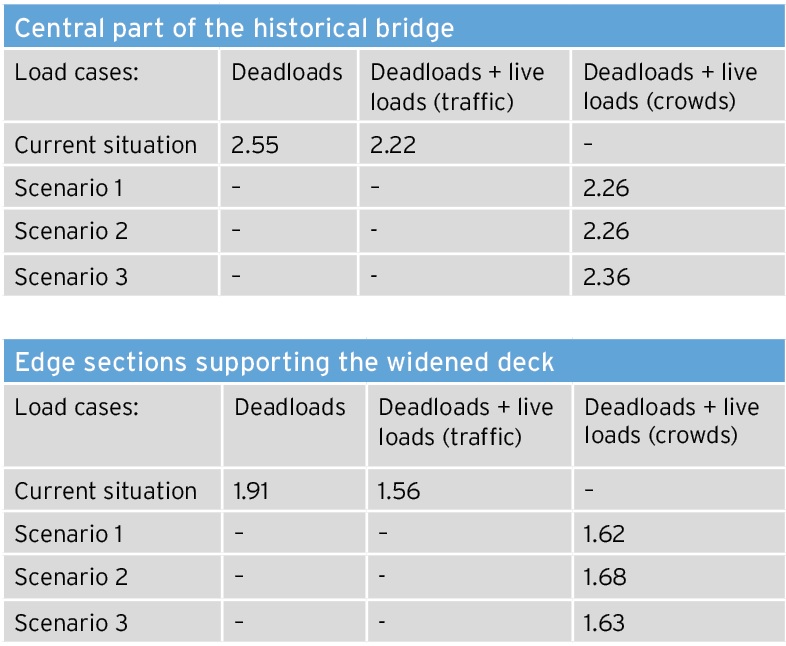 Results of the rupture factors according to load cases for both parts of the masonry vault
The various scenarios raise the value of the coefficient of rupture, which are actually closer to 3 in the current usage, where live loads are taken into account in the central part only. Scenario 2 is the one that has the highest rupture factor, where the combination of deadload and crowds is slightly higher than on the bridge in service today. Further detailed analysis, based on additional research and investigations remains to be carried out.
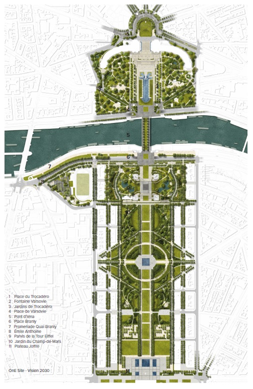 Landscaping plan around the Eiffel Tower(Gustafson Porter)
In summary, we found that not only had the spare capacity of the bridge already been used in its 1937 widening, but also that the bridge’s current loading was higher than is recommended, even if no issues have presented at the abutments. Our study has shown that it is feasible to go beyond a simple pedestrianisation project and instead enable transformative landscaping through limiting the surface of the lawn to the central zone of the original bridge. Works on site are due to start after the 2024 Olympic Games of Paris.
We would like to thank the partners of the project design team, Kathryn Gustafson and Mary Bowman as well as the entire team of Gustafson Porter & Bowman, and the architectural practice Chartier & Corbasson.
Niccolo Baldassini is technical director, Pierre Marquis Lhuillier is structural engineer and architect, Klaas de Rycke is managing partner – all are at Bollinger & Grohmann, Paris. Kenny Verbeeck is managing director, Bollinger & Grohmann, Brussels.
References
[1] MERY E, “Sur l’équilibre des voûtes en berceau”, Annales des Ponts et Chaussées, 1840.
[2] SALENCON J, Calcul à la rupture et analyse limite, Presses de l’ENPC, Paris, 1983.
[3] COULOMB CA, “Essai sur une application des règles de maximis et minimis à quelques problèmes de statique, relatifs à l’architecture”, Mémoires de Mathématiques et de Physique présentés à l’Académie Royale des Science par Divers Savans et lus dans ses assemblées, Vol 7, Paris, 1773, pp343-382.
[4] HEYMAN J., “The stone skeleton”, International Journal of Solids and Structures, Vol 2, 1966, pp249-279.
[5] DELBECQ J-M, Les ponts en maçonnerie, Ministère des Transports, Direction des routes, SETRA, 1982.
[6] « Fascicule n°61. Conception, calculs et épreuves des ouvrages d’art. Titre II : Programmes de charges et épreuves des ponts-routes. » Cahier des prescriptions communes applicables aux marchés de travaux publics relevant des services de l’équipement. Ministère de l’équipement et du logement, 1971.
[7] International Recommendations for Masonry Structures – CIB Report – 1958.