Later this year China’s new Taizhou Bridge over the Yangtze River is set to open to traffic, marking the inauguration of yet another major bridge crossing of this mighty waterway. But the bridge is not just a long-span crossing, it is a multi-span crossing, with each of its two consecutive main spans stretching to more than 1km in length. On completion it will be the world’s longest-span bridge of its type, but designing and building a multi-span suspension bridge, particularly on this scale, is not a straightforward process.
The main structure of the Taizhou Bridge project is a three-tower suspension bridge with two consecutive main spans of 1,080m and side spans of 390m. The bridge is a major element of infrastructure development in the east of China and will play a vital role as a link in the freeway network in Jiangsu Province and the Yangtze River delta region. It is part of a new 62km-long freeway that links the cities of Taizhou, Zhenjiang, and Changzhou, which is being built at a cost of US$1.5 billion – the bridge itself has cost US$400 million to construct.
In general, a multi-span suspension bridge is simply an enhanced suspension structure with an additional central tower; in this case it has been chosen in order to reduce the number of bridge piers in the river, and hence minimise the impact on the water flow. But the characteristics of a three-tower suspension bridge are markedly different to those of a traditional suspension bridge.
At the bridge site, the river is some 2.1km wide and the riverbed has channels at each side with a shallower water depth in the centre, with a w-shaped cross-section. The deepest channel is on the south side and has a water depth of approximately 30m while in the middle of the river this reduces to approximately 17m.
Both banks of the river are typical middle and lower Yangtze River alluvial plains which consist of soft soil and a thick cover layer and the depth to bedrock is generally at least 190m. A three-tower suspension bridge design was chosen in order to minimise the impact on river flow, expedite the development of port facilities and to make navigation easier.
This solution minimises the number of bridge piers in the river, to reduce the obstruction to water current and retain sufficient openness of the river. Multi-tower suspension bridges, which have the advantage of length and sequential spans, are expected to increase in popularity in coming decades as an important option for large-scale sea crossings.
Three-tower suspension bridges such as this can overcome the limitations of single span structures, creating a continuous crossing. Such multi-span systems have often been proposed for use on sea-crossing schemes, but of those which have reached completion, the longest span is just 210m, which is far from the capacity of such a structure.
The Taizhou Bridge is the first attempt to create a long-span multi-tower suspension bridge. Such a bridge is essentially an improved suspension structure with an additional central tower, vertical support of the main cables, at the mid span of single main span suspension bridge, in order to reduce the internal forces of the main cables and anchors. The central tower saddle acts only as a vertical support point for the main cable.
Under dead load, the restraint placed on the middle tower top by the main cable is less than that of the side towers. Three key issues must be resolved to successfully design a three-tower suspension bridge. Firstly, under the most unfavourable loading conditions with all live load on one main span and none on the other, the vertical deflection of the deck must be controlled within a reasonable range. Secondy, the friction between the saddle and the main cable must be such to prevent the cable from sliding.
While meeting these two criteria, the safety and stability of the central tower must also be assured. The longitudinal stiffness of the middle tower must be sufficient to allow flexibility and bending stiffness to suit the characteristics of a three-tower suspension bridge system. Three tower types were considered: an inverted Y-shaped tower, an A-shaped tower and an I-shaped tower. The middle tower was designed to be formed of two A, I or Y-shaped elements, placed one each side of the deck, along the longitudinal axis of the bridge rather than straddling the deck.
The results revealed that the I-shaped tower has a low stiffness, and that deformation of the tower top and deck would be too high under the most adverse conditions. The disadvantage of the A-shaped tower is its low friction safety factor. However the inverted Y-shaped tower offered a reasonable friction safety factor as well as a reasonable value for the tower section stress and main girder deflection. For this tower design, an appropriate stiffness was selected based on extensive calculations of different control parameters, including the tower height, cross-section, the longitudinal distance between the tower feet and the height at which the tower legs join.
For this particular design, when the height at which the legs join is kept constant, and the tower section size is known, the longitudinal stiffness of the tower first increases and then reduces, as the distance between the bases of the tower legs increases. This stiffness is at its maximum when the feet are between 30m and 35m apart. At this range, the minimum axial pressure of the tower bottom increases; when this distance is less than 32m, the minimum pressure is negative at the tower base. The feet should be more than 32m apart in order to avoid tension forces at the bottom of the tower section.
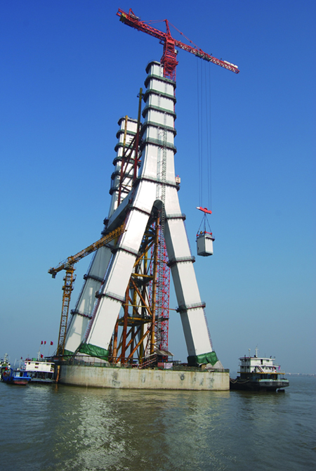
As the bifurcation point is raised, the longitudinal stiffness becomes greater and the anti-slipping safety factor reduces. According to the force transfer mechanism of a three-tower suspension bridge, the middle tower must be suitably rigid in the longitudinal direction with proper flexibility and sufficient bending rigidity. After calculating and comparing multiple structural forms, a longitudinal inverted Y-shaped, transverse portal-type frame steel tower 200m high was selected for the central tower. The tower feet are spaced 34.75m apart and they connect at a height of 69.5m.
The foundation for the central tower, which is located in the centre of the river, is a caisson structure with cross-sectional dimensions of 58m by 44m. It has a total height of 76m, split into two parts each 38m high. The lower part is a prefabricated rectangular steel-shelled structure, while the upper is a concrete caisson.
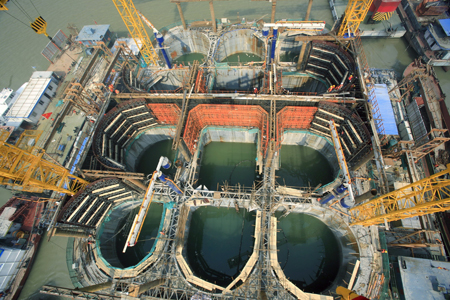
The first part of the steel-shelled caisson was fabricated onshore, then floated in the water where construction continued, extending it to its full 38m height. It was then floated and tugged to its permanent location, where it was placed on the riverbed by flooding it with water. Once it was in position, the chambers of the steel-shelled structure were filled with concrete, gradually extending it above the steel shell, to the final design elevation.
Underwater concrete casting was used to complete the foundation construction. The connection between the concrete cap and the steel tower needed special consideration. If the tower steel plate had been cast directly into the concrete cap, the axial force from the tower would mainly transfer by anti-shear between the steel plate and the concrete. It would be possible to set shea