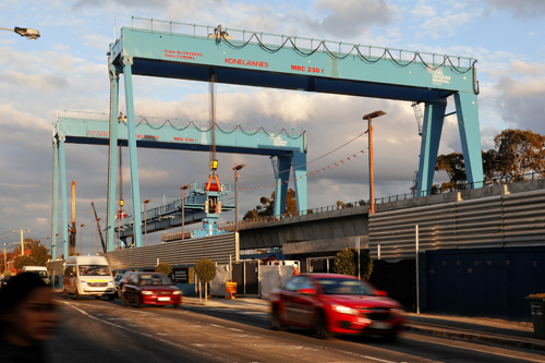
The project featured the first use of a straddle carrier and gantry crane configuration in Australia, an innovation that was made possible thanks to the freedom the client allowed the contractor in developing the construction solution. The US$1.2-billion Caulfield to Dandenong Level Crossing Removal Project was intended to substantially improve highway traffic flow in an area where, over the two-hour morning peak, it could be at a standstill for a total of 87 minutes due to the lowered boom gates. The project was also designed to deliver a more reliable train service with a 42% increase in capacity.
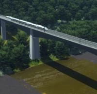
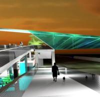
The scheme entailed the removal of nine congested level crossings along Melbourne’s busiest rail line, the Cranbourne-Packenham line; the separation of the rail and road networks by construction of a new 3.5km-long elevated rail viaduct; and the rebuilding of five stations. The raised railway line will also create 225,000m2 of public open space, including 12km of pedestrian/cycle paths and 300 parking spaces around Clayton Station.
The project is being delivered by an alliance consisting of Lendlease, CPB Contractors, WSP, Aurecon, LXRA and Metro Trains Melbourne, with Lendlease and CPB Contractors working as a construction joint venture and WSP and Aurecon as a design joint venture. LXRA is the client - the Level Crossing Removal Authority — which is also part of the alliance membership. The non-owner participants are in unincorporated joint ventures, with their time on the project being reimbursed by the LXRA.
Construction director Simon Barnes recounts that at the start of the project, the contract bidders had an unusual amount of freedom as regards the solution for the level crossing removal — even down to whether there should be an elevated rail line at all. “One of the interesting things about this project is that the client had said to the market, ‘we need to remove nine level crossings, we are not going to fix you into a reference design, we want to see all the best innovation that can come from the market on how we do it’.”
During the bid phase, Lendlease had concluded that, for this particular line, taking the rail over the road would be the best solution in terms of cost and disruption. This would also free up land underneath the viaducts for public parks, car parking, bypass construction and improved connectivity for the public. “From an environmental sustainability perspective it was far more effective too, with less material, fewer trucks on the roads, and less digging into the road,” says Barnes. Thoughts then turned to construction methods for the section of the twin elevated railway viaduct that was to replace four of the nine level crossings. The challenge here was that construction activities would be along a narrow rail corridor next to, and above, the existing operational rail line, with no access from the sides.
An underslung gantry system had been considered, but was rejected because such a method would have still required a degree of access to the structure from the side. What was needed was a fully linear installation solution. “At that point,” says Barnes, “we approached VSL, with whom we [Lendlease] had had a long positive relationship, and we partnered to work on a solution. They had built 22km of viaduct in Taiwan using a very similar technique and a carrier gantry system. They proposed it to us and we started to work on the details together.”
For the other section of the rail viaduct, incorporating the five remaining level crossings, a different construction method was decided on. “For the other section we used what we call ‘super-T’ concrete beams, because we could park cranes and install full spans quite comfortably. In addition, we did not have the capacity to achieve the construction programme by using the same construction method in both areas. Using the different methods we could get the supply of precast elements we needed.” Installed side by side, the precast concrete, T-shaped beams form the elevated rail deck at Noble Park and Clayton, where the rail corridor was wider.
To construct the areas with no side access, two 94m-long mechanised support beams and a 63m-long straddle carrier were purchased from Deal. Once in Melbourne, VSL staff who had worked on the project in Taiwan were involved in training staff to drive the carrier and operate the equipment for the installation of the spans.
The super-elevated structure consists of simply-supported precast segmental spans. Concrete segments of 3m by 5.5m by 3.2m — typically weighing around 30t — were cast in a 54,000m2 precast yard and transported to site by road to feed the work cycle, with installation of the spans beginning in September 2017. The majority of the spans of the elevated rail sections are 40m long and 435t in weight, with a number of 27m spans in the vicinity of stations, to accommodate the additional loading required.
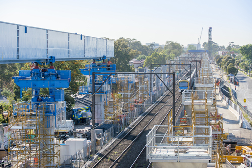
The stressing yard was located at the mid-point of the 3.2km-long twin viaducts, at Murambeena Station. Here, the installation process proceeded as follows, with the twin viaducts being erected in parallel. The concrete segments were assembled, stressed and then lifted onto the elevated rail deck, using two 230t gantries. The gantries then lifted the 270t straddle carrier and positioned it above the span.
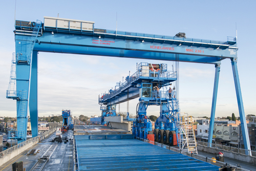
The straddle carrier lifted the concrete span and moved forward at 2.5km/h, guided by an automatic steering system along a wire rope. When it reached the working edge of the deck, the straddle carrier engaged with a 94m-long self-launching steel support beam which was positioned over the location of the new span. A trolley on the beam connected with the straddle carrier using two jacks, raising it by around 640mm, and leaving a 400mm gap between the straddle carrier tyres and the deck. After the trolley and the straddle carrier had been coupled together hydraulically and electrically, the two were pulled forward by a chain system driven by hydraulic motors.
Once the straddle carrier and the new span were in position at the final location, the same hydraulic system removed the support beam so that the span could be lowered. With the span in place, the beam then reversed sufficiently so that the straddle carrier could be released from the trolley jacks, and lowered onto the new span. The straddle carrier then returned to the assembly area, where the gantry cranes had already placed another concrete span on the adjacent rail deck, using steel screens to protect the live rail line below. The straddle carrier was then transferred onto the span on the adjacent deck, and the process repeated, using a second support beam, thus erecting the two decks in parallel.
In the first phase, construction progressed towards the city centre; once that section had been completed, the equipment was turned around so that the remainder of the viaducts could be built in the opposite direction. Curvature was so slight in the areas where the straddle carrier was used that any lateral adjustments could be made using a jack, once the initial span installation was completed.
Even though this full-span erection method is used extensively on high-speed rail projects in Europe and Asia, the application in Melbourne had a notable difference, explains Deal project engineer Michele Parola: “Construction took place in a narrow rail corridor through busy residential suburbs and in some places only 5.5m away from fences: this was a significant constraint on the equipment design.” As ensuring the safety of residents, workers and commuters was key, the straddle carrier was designed with the latest cable guidance technology, both to prevent the carrier from deviating left or right, and to ensure it moved with 100mm precision along the centreline of the elevated rail deck. “This was crucial because the massive, 4.7m-wide machinery had to safely move along a 5.2m-wide corridor on a deck at a height of 11m, surrounded by residential and industrial buildings, railroad pylons, and with trains and road traffic below,” says Parola.
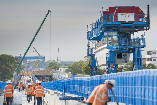
Construction had been planned to continue through the night, hence another challenge was keeping noise levels to a minimum so as not to disturb residents. This was achieved by a dedicated design that included large amounts of insulation around noise-making components. For the engineers, however, there were a few sleepless nights during the installation of the first few spans, as they started along the steep learning curve towards achieving confidence in the new technology. “At the beginning of the process, the first span took five days,” says Barnes. “By the end of our best day we got four spans in a single day. I think for the first ten spans we allowed two and a half days per span, but pretty quickly we got into the cycle of doing two spans per day.” By March this year, a total of 174 bridge spans, each ranging from 280t to 420t in weight, were in place, and trains started running in June.
In hindsight, Barnes cannot think of anything that he would have been done differently. “We picked the right method and it worked, no question of that.” He is positive that the straddle-carrier construction method will be used again in Australia, next time the circumstances are right. He points at the elevated rail being constructed in Sydney as part of the Northwest Rail Project, where there have been reports of issues with stressing, in the post-installation phase. “Our method has the advantage that you do the stressing on the ground so any issues with stressing become apparent well in advance of lifting,” he comments. For Parola, this project is an example of how the combination of highly specialised equipment and state-of-the-art control systems can lead complex and usually slow heavy-lifting operations through to reliable and highly productive activities with no reduction in safety levels.
The project is expected to be completed by the end of this year