Earlier this year, the methodology developed for destressing and cutting strands during the replacement of two cable pairs on the southern structure of the Galecopper Bridge was successfully put into practice. The operation ran largely according to plan, but – as is often the case with complex engineering interventions – there was a brief moment that prompted a pause for consideration.
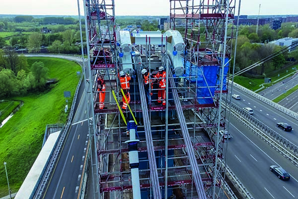
Attaching new PE sheaths to the deviation saddles on Galecopper Bridge
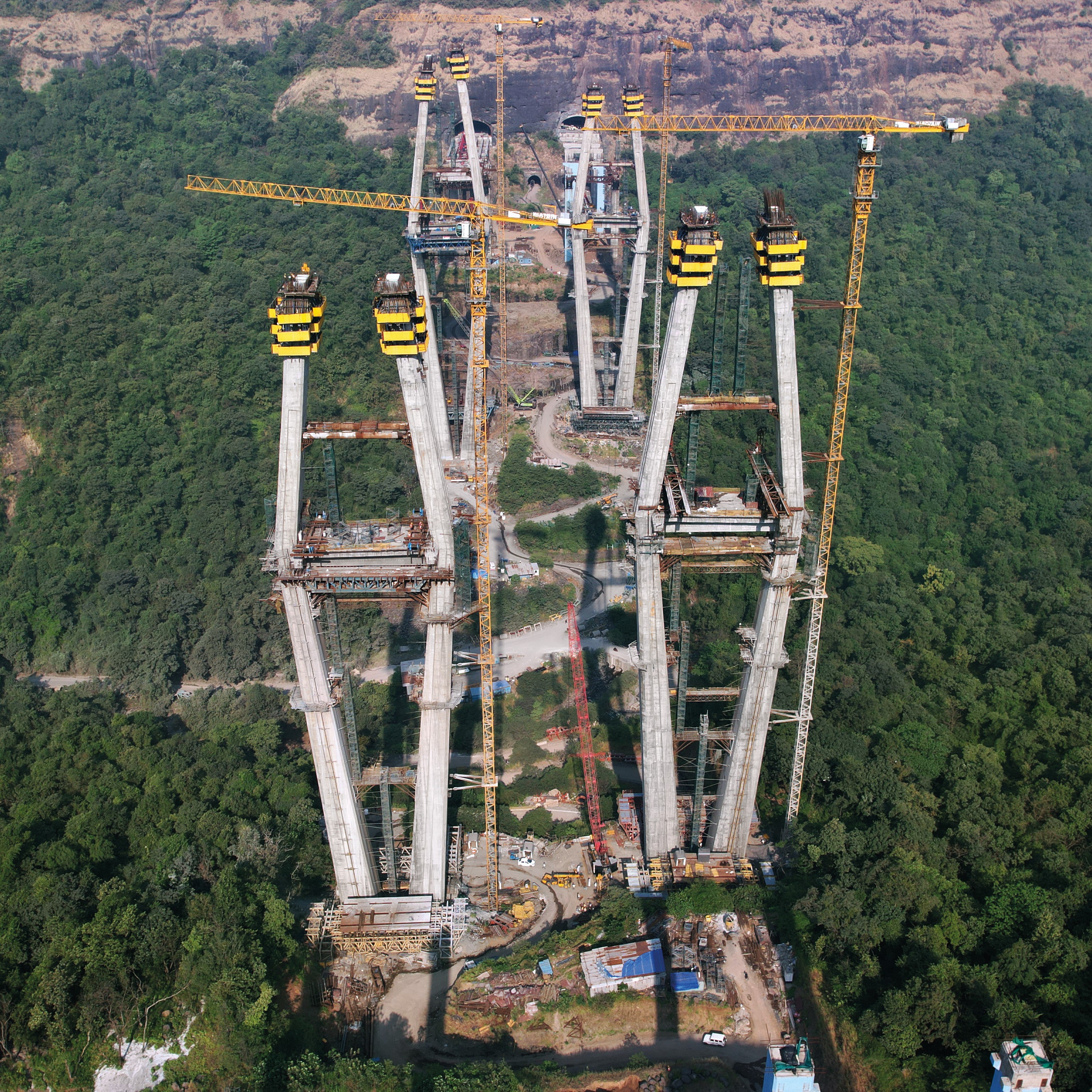
Located across the Amsterdam-Rhine Canal in south-west Utrecht, the 326m-long Galecopper Bridge has undergone significant maintenance operations in the last 15 years, many related to the development of fatigue cracks on its orthotropic deck caused by increasing traffic loads and volumes. The bridge supports around 80.3 million vehicles annually, 8-12 million of which are heavy goods vehicles.
Each twin structure features a 180m-long cable-stayed span supported by two pylons, with each pylon carrying a pair of stay cables that pass continuously over a steel saddle. The orthotropic deck is 34m-wide and 3.3m deep.
Between 2013 and 2015, multiple interventions were carried out on the structure: a thin layer of UHPFRC was added to the deck; 327m-long independently supported steel beams were installed along both sides of the deck for a potential future widening project; and the existing bearings replaced with spherical bearings. During this work, the deck was also raised permanently by approximately 1m to allow vessels travelling on the Amsterdam-Rhine Canal below to carry an additional layer of containers.
It was during this intervention that corrosion was identified on some of the wires located within the space between the anchor plates and the anchorages on the south twin’s deck, found to be caused by pooling water that was polluted with de-icing salts and particulates. Subsequent waterproofing details and the addition of a new cable dehumidifying system failed to arrest the further snapping of wires, however: the rate of wire breaks appeared to increase, at least in a first phase. Extensive monitoring was carried out during this time and, according to owner Rijkswaterstaat (RWS), the structure was safe to use.
In 2019, RWS decided to replace the entire cable system and later awarded the contract to KWS, Freyssinet and CT de Boer, with Arup responsible for detailed design.
The existing stay cables consisted of six locked coil strands (containing 201 wires each) anchored at the deck: the scheme envisaged replacing these with continuous cables threaded through deviation saddles placed next to the existing steel saddle, which would later be removed. Each pylon would therefore carry two pairs of cables anchored to the girder in front and behind the location of the former cable anchors.
The new stay cables are formed by 65 PE-sheathed strands containing seven wires, each strand individually threaded and channelled through a deviation saddle formed by a steel box surrounding the UHPFC matrix featuring an individual recess for each strand.
Towards the end of 2023, Jurgen Jochims, director at Freyssinet, told Bd&e that the most challenging aspect of the project was the development of a system for safely cutting the strands and transferring the load to the new cable strands. At the time, a solution had been designed that was undergoing testing in Switzerland (Bd&e issue 114).
A year and a half later (September 2025), Bd&e took up the conversation again, this time with a visibly more relaxed Jochims: the system had worked as expected and the Freyssinet team was 100% happy with the result. All the cables had been replaced, and the bridge was planned to revert to its original traffic configuration by the end of the year.
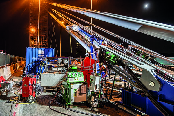
The solution that was implemented was carried out with minimal impact on highway traffic – the bridge was reconfigured with narrowed carriageways, one slip road closed, and necessary closures scheduled for periods of only five hours during the night for the cutting operations.
The carefully planned and managed operation for cutting the 24 locked coil strands - each 76mm in diameter – followed a series of identical eight-day cycles. First, 22 new strands would be individually threaded through the four ducts on either side of the pylon, and the deviation saddle recesses, then secured and tensioned to a starting load of 85kN on the first of them. Thereafter, a locked coil strand would be slowly prised out of the bundle on each side of the tower, using a combination of wedges, hydraulic pump and chains. With a strand sufficiently separated from the bundle, the specially designed clamping system could be fitted: 12 clamping blocks, all in a line and each secured with six single-use bolts. Next, a crossbeam would be added in front of the furthest clamp.
Strand jacks that had been temporarily anchored to the deck could then be used to pull on the crossbeam with a force of around 150t, relieving the tension at the lower end of the strand, near the deck, so that the remote-controlled diamond saw could cut the strand. Lastly, the jacks would be slowly released, gradually redistributing the tensile forces amongst the new strands.
The bypass solution for cutting the strands included the use of clamping blocks (seen in blue), crossbeam and hydraulic jacks
“It took five days to prepare and, on the sixth, we would do the cutting. The seventh day was rest for the team, because of the nighttime work, and on the eighth day we would release the cut cable,” says Jochims, adding that to maintain equilibrium the operations alternated between cable bundles on the left and right side of existing cable pairs.
As in any complex operation, and especially for one as unusual as this one, there were plenty of discussions around every step of the proposed process.
Ahead of the works, one point for discussion revolved around establishing the initial number of strands to be installed and the pre-tension force. Matthieu Guesdon, business activity manager for post-tensioning and stay cables at Freyssinet, explains that this was quite a balancing act: “The idea of the tensioning sequence was to limit the eccentricity on the saddles, but also to limit the amount of load that was transferred to the deck and the existing cables, which were in critical condition. The utilisation ratio of that deck was on the very limit, so too much load on the cable would mean a high risk of damaging the steel/concrete deck. We were basically having to balance adding enough strands to compensate for the strand we would remove, but not too many that we move to a critical zone for the steel deck. We also discussed the load we should start with, as this would be the largest, so that that we would be at the right level of load when it came to strand 65.”
As Freyssinet and Arup used different software for the load assessment, both teams had to ensure that they were using the same assumptions for the self-weight of all elements, including the stay cables, fire protection and ducts. “We also had to ensure that – even if there were differences [in the results] – that they remained within tolerances of modelling, and that we weren’t understanding the behaviour in different ways,” says Guesdon. Some of the calculations also had to take place in step with in-situ works: the as-built geometry of the cable could not be ascertained until the removal of the pylon cap.
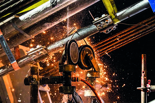
The 76mm-diameter strands were cut using a remote-controlled diamond saw
In common with many complex engineering interventions, there was one unexpected occurrence. During the installation of strands 1 to 12, on the western pylon, the force needed by the strand jacks to detension the lower sections of the existing strands was lower than anticipated. “We could clearly see a sag in the cable length, which indicates zero tension,” remembers Jochims, “And the load cells on the existing anchorages showed there was no force in the cable.”
This caused some head-scratching because while there were procedures in place for ‘no go’ occasions at three steps of a cutting night – for example if there were higher tension loads at the jacks – there was no planned procedure for the opposite case, where load was too low. Discussions followed on the potential causes of this lower load and what – if anything – should be done. At the time, the monitoring and the surveying equipment showed every geometry within tolerances, “And the difference with loads was within 10% difference with the higher forces in our strands,” says Freyssinet technical manager Reno Couwenberg. Together with Arup, it was decided to proceed, “It was quite early in the cycles so [the plan] could be adapted later,” says Couwenberg.
Whether the plan should be altered was discussed after the first cycle, and a number of options were considered. In the end, however, it was felt no changes were necessary because at the end of each cycle the strands reached their expected load of around 45kN per strand. “It’s reasonable to expect that new strands just take over more load,” says Guesdon: “So if there is somewhere a bit more stiffness, the cables are maybe stressed a bit higher. It’s probably a summation of all these effects that resulted in more load than expected in the new strands, and therefore the cable loads in the existing cables were lower.”
As the cycles progressed, the old strands were fully removed from the structure, providing an ideal opportunity to ascertain their exact condition. While samples have been duly retained for in-depth testing, simple visual inspection of the samples have indicated some corrosion in the free length of the strands, including wire breakages, as well as corrosion in areas of the strand previously covered by the fire protection system.
Back on site, finishing works are under way, including installation of handrailing for the evacuation pathway beneath the bridge and corrosion protection on the western pylon’s new saddle cover. Railing on the deck remains to be reinstalled, as well as signage and lighting.
The Freyssinet cable team left site at the end of July and, by all accounts, the success of the Galecopper Bridge’s cable replacement has sparked interest from bridge operators and owners with similar designs and issues.
Client: Rijkswaterstaat
Client’s engineer/designer: Arup
Main contractor: KWS
Subcontractor of stay cable replacement: Freyssinet
Steel strengthening: CT de Boer