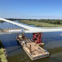
With the start of the new year, contractors on the Waal Bridge on the A50 motorway near Nijmegen in the east of the Netherlands will begin the process of replacing all of its cable stays. This work forms part of a larger renovation contract which has been under way since last year, but is one of the most complex and crucial parts of the project.
The bridge is one of eight bridge structures which client Rijkswaterstaat, part of the Dutch Ministry of Infrastructure & Environment, selected for renovation due to problems with fatigue cracking in the orthotropic decks. Until the renovation and strengthening of these typically 40-year-old landmark bridges can be completed, they are under a stringent regime of inspections, and repairs as necessary.
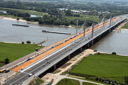
The bridge crosses the River Waal, which is the main branch of the Rhine in the Netherlands, and as such is a vital transportation route between the Port of Rotterdam and mainland Europe. The bridge was opened to traffic in 1976, and the 1,055m-long structure has ten spans with a 480m-long cable-stayed section over the river.
This part of the bridge has a main span of 270m and back spans of 105m on each side. The deck is a steel trapezoidal box girder with orthotropic plates to the top and bottom flanges. The box girder is continuous over the ten spans and supported by cable stays over the river crossing and the adjacent back spans.
All the cables are located along the central longitudinal axis of the bridge, with each plane consisting of an upper and a lower set of cables. The upper set contains two bundles of five locked coil cables, and the lower set contains two bundles of three locked coil cables. Each cable has an external diameter of 101mm and a minimum breaking force of 903t per cable and they all run uninterrupted over the cable saddles in the tower.
An assessment of the existing cables suggested that approximately 70% of the capacity was in use under the present loading situation, without allowing for any reduction in capacity due to their condition. Although this might be considered an acceptable loading situation, the demands on the cables are set to change with the renovation of the structure.
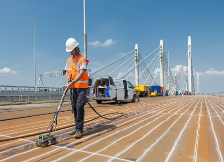
The primary issue which the renovation is set to address is local fatigue problems in the deck plate as well as global static capacity deficiencies. This will be done by the application of a high-strength concrete overlay to the steel deck plate, which will significantly increase the static loading to be carried by the box girder and the cables.
A second bridge has been built next to the existing structure; this photo shows the new bridge on the left.
After renovation, analysis suggests that the cables will be carrying 85% of their design capacity, again without allowing any loss of strength due to their condition. Moreover, inspections of the locked coil cables have identified that they do have defects, principally the presence of microfissures which have resulted in a number of wire fractures along the length of the cables.
A numerical probabilistic assessment of the design capacity of the existing cables concluded that a 30 year remaining life of the cables could not be guaranteed. This factor, plus the proposed increase in loading, was central to the decision to replace all of the existing locked coil cables as part of the overall renovation programme.
The managing contractor, a joint venture of Arup, Royal Haskoning DHV and Greisch, is responsible for the renovation of all eight bridges in the RWS programme, and defined various criteria for the cable replacement works, including the need to maintain the existing structural behaviour of the bridge and avoid the use of temporary supports in the river and flood plain. Constraints on the contractor had to be minimised during the works, and the process was required to have no negative impact on the other renovation measures. The specification also had to minimise the potential for defects in the new cables and enable the works to be completed in a short time frame, once the traffic had been removed from the bridge.
The reference design investigated several cable types, including a parallel strand system. This system was not advanced during the reference design stage as the proprietary saddle systems available on the market were not able to accommodate the 192 strands which would be necessary for the long cables. A like-for-like cable replacement system was initially selected, proposing 100mm diameter, locked coil cables with similar structural characteristics as the existing cables, in terms of strength and stiffness.
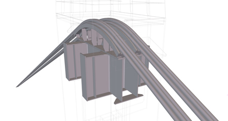
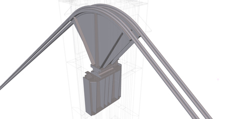
Diagrams showing the existing upper and lower cable saddle arrangements on the towers.
The cable specifications also included stringent fatigue testing requirements. Under the like-for-like system, it was proposed that the existing saddles in the tower and the anchorages in the box girder could be reused. The original design of the Waal Bridge did not consider the replacement of cables, hence there was no option of replacing the cables one by one, or even bundle by bundle, and more extreme measures were necessary. The proposal is to effectively reverse part of the original construction process in which each set of bundled cables was tensioned by jacking up the saddle support beams within the tower.
When the desired cable force had been reached, bolt holes were drilled through an end plate on the saddle support beam to connect the beam to the tower. At the cable anchorage in the box girder, a deviator separates the cable bundle into a fan of cables which are then anchored in the box girder. There is restricted space behind each of the anchor heads in the box girder and this configuration does not allow cables to be de-tensioned independently. At each cable saddle, the cables in each bundle are configured in two rows, with cables in the upper row sitting directly above those in the lower row. As each of the existing saddle support beams support both bundles of cables, it would not be possible to de-tension the bundles of cables independently.
Hence, replacement of the cables will be undertaken using a sequence which involves de-tensioning one cable set fully, and replacing that set of cables with new cables using the strand-by-strand installation method. This operation will be repeated for each subsequent set of cables. The envisaged method of de-tensioning and removing the existing cables is by jacking down the cable saddle support beams from the upper position. Tensioning the new cables will be carried out strand by strand through the multitube saddles once they have been jacked back up to their original position. The modularity of the parallel strand system and the Freyssinet anchorage minimises the risk of cable procurement compared to using a locked coil cable.
The final length can be adjusted on site before the threading operation, and the required load can be adjusted during the stressing operation. No temporary supports or temporary cables are envisaged. This has only been made possible by the opening earlier this year of a new concrete cable-stayed bridge adjacent to the existing Waal Bridge. The co