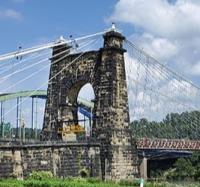
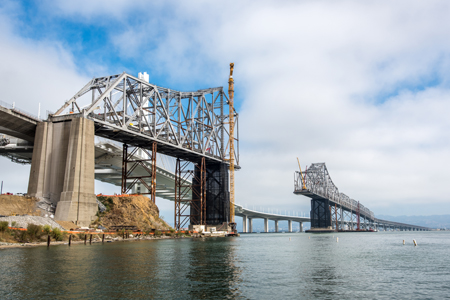
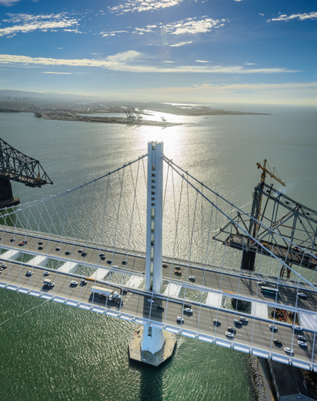
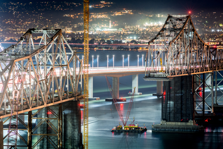
With the opening of the new eastern spans of the San Francisco - Oakland Bay Bridge in 2013, the original crossing finally became redundant. For more than 75 years it had served as a vital transportation link in the San Francisco Bay area, in its recent years carrying some 270,000 vehicles per day. But after the 1989 Loma Prieta earthquake exposed the deficiencies of the eastern span, the decision was taken to build the new crossing. The signature self-anchored suspension bridge now towers over its predecessor, an iconic cantilever truss structure that served as the ‘workhorse’ of the bay area for so long. With the construction of the new bridge coming to a close, attention shifted to the unique challenges posed by dismantling the original bridge which was located, at its nearest point, only 100mm from the new structure.
In 2012 bridge owner Caltrans awarded the first contract for the bridge dismantling, including the cantilever truss spans, to a joint venture of California Engineering Contractors and Silverado Contractors. Foothills Bridge Co was selected by the joint venture as the contractor’s engineer of record. With specialised experience in engineered bridge dismantling, the firm provided the joint venture with a detailed dismantling plan including the bridge dismantling sequence, required jacking forces and displacements, and design loads for temporary truss members and temporary support towers. Foothills Bridge Co also designed temporary steel supports for the bridge dismantling and provided an onsite engineer to support the dismantling operation. The project specifications required a second engineer to provide an independent check of the dismantling plan, which was provided by consultant FBA.
The eastern structure consists of the cantilever truss spans and several approach spans. The cantilever truss features 155m-long anchor arms at each end and a 428m-long main span consisting of the cantilever arms and suspended span. The structure has steel truss and bracing members built up from plates and rolled shapes. The chords and larger diagonals are box shaped with solid plates on all four sides and lighter members are latticed with lacing angles and/or bars. High strength eyebars are used for chords and primary diagonals with large tension loads. The bridge supports two decks, with the original configuration providing for train and truck traffic on the lower deck and automobile traffic on the upper deck. In the 1960s the bridge was retrofitted to remove train traffic from the bridge; in its final configuration, five lanes of westbound traffic were using the upper deck and five lanes of eastbound traffic the lower deck.
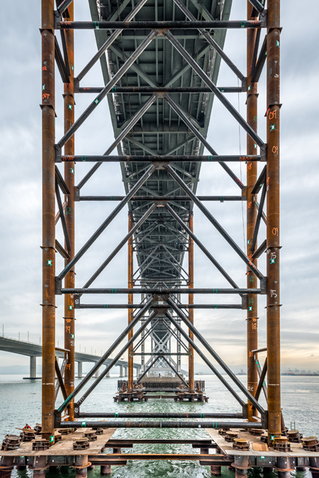
The temporary bents underneath the anchor span sit on top of marine foundations supported by pipe piles which were driven up to 50m deep to reach solid strata.
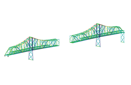
An accurate dismantling plan for the bridge relied on the creation of a precise 3D finite element model so that member stresses and displacements could be accurately predicted. A finite element model of the bridge was created by Foothills Bridge Co using Lusas Bridge analysis software. This software package allowed modelling of the sequence through staged construction which enabled engineers to model the installation and removal of truss members sequentially. Loads applied to the structure could also be applied at different stages of the sequence.
In order to develop an accurate model of the bridge, all member cross-sections and weights were determined; this required a thorough review of the 1930s as-built fabrication drawings provided by Caltrans. These drawings made it possible for the weight of all members and connections to be accurately represented in the model. Using all section properties, member weights, and deck weights, the model was then benchmarked against the original design. The original design drawings included stress sheets that provided the designer’s member forces as well as pier reactions. The benchmarking process ensured that bridge member forces and reactions could be reliably predicted. Once the model had been benchmarked to the original construction, it was updated to incorporate the various retrofits that had been carried out since construction. This included modifying the deck weight and updating the floor system.
In addition to considering the bridge geometry, section properties, and weights, the actual erection sequence of the original bridge was taken into account. Generally, the bridge was constructed by starting at the two ends and building toward the centre of the bridge. This process involved the use of temporary support towers in the anchor arms as the bridge was constructed toward the interior bridge piers, and then cantilevering the bridge out to midspan before connecting the two halves. In this erection sequence, each half of the suspended span was erected as an extension of the opposing cantilever arms. After the two halves were joined, the suspended span was ‘swung’ by disengaging the upper chord at the ends of each cantilever arm so that the span became simply supported at the end of the cantilever arms. This operation allowed the bridge to settle into its service configuration.
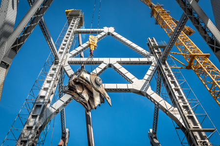
With the 1930s era connections made up using rivets or large-diameter pins, heavy knuckles were removed whole and lowered to awaiting transport.
Initially, it appeared that the original erection sequence would not have much influence on the output of the model. However, as the erection sequence was studied in greater detail, it became clear that during several stages of construction, the bridge was jacked at various locations to allow for fit-up of members and to ensure that the deformed shape of the bridge was correct. This jacking resulted in locked-in erection forces that needed to be considered in the model. Modelling this erection sequence was critical in the development of an accurate model.
The bridge dismantling sequence proposed by the contractor approximately reverses the construction of the bridge. The proposal was to dismantle the bridge piece by piece using equipment that would be placed directly on the structure. The known erection sequence, which was useful in generating the accurate finite element model, also proved helpful in establishing the dismantling sequence. The primary difference between its erection 80 years ago and the current dismantling is the dead weight of the bridge. In the original erection sequence, the concrete deck was not added until the full truss was complete, and the equipment used generally consisted of lightweight derricks.
For an efficient dismantling process, the contractor wanted to use large cranes operating on the bridge’s lower deck, which means that the lower deck has to be removed panel-by-panel just ahead of the truss. It was possible to remove the upper deck in advance, but the weight of the lower deck and the considerably larger equipment created challenges during some stages of dismantling.
The first major milestone for the dismantling was to disconnect the two halves of the bridge at midspan. In order to do this, it was necessary to re-engage the upper chord of the suspended span to the ends of the cantilever arm. But in order to cut the truss members at midspan without a large release of energy and large displacements, the simple re-attachment of the chords was not sufficient. A jacking procedure was necessary to relieve the compression in the upper chord and the tension in the lower chord of the suspended span. Analysis showed that the truss did not have adequate capacity for this to be carried out while the concrete on the lower deck was still in place. Hence it was necessary to remove the concrete deck of the suspended span before re-engaging the upper chord. Access for equipment and personnel was provided by the installation of timber mats on the suspended span. With the known dead load of the bridge and known equipment loads, an iterative analysis was used to determine a jacking sequence that minimised the force in the midspan members as they were cut.
The procedure was to jack the upper chord with approximately 8,900kN of force (approximately 130mm of displacement) in each truss at both ends of the suspended span upper chord. This force was sufficient to remove the compression in the upper chords, however the locked-in forces from the erection sequence meant that the lower chord still retained a small, but not insignificant, amount of tension. This was relieved by jacking apart the split bent at the eastern end of the bridge, shortening the lower chord and reducing the tension at midspan. The required jacking force in the lower chord was 1,100kN per truss, or approximately 80mm of displacement.
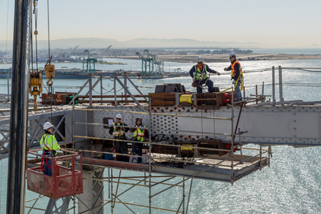
Crews work to re-engage the suspended span upper chord, applying nearly 9,000kN of tension with hydraulic jacks.
This operation was considered one of the most critical and technical steps of the dismantling sequence, and was carefully planned and executed. Prior to jacking, displacement monitoring survey points were chosen and benchmarked and they were continuously monitored during the operation to ensure the behaviour of the structure reasonably reflected the predictions of the model. The observed displacements during upper chord jacking compared favourably to those predicted by the model, giving the contractor a high level of confidence as dismantling continued.
Having completed the upper chord jacking, attention shifted to the next major milestone: completion of the cuts that would split the cantilever structure in two. The jacking sequence could not ensure zero residual force in the five members in each truss that had to be cut, hence the procedure was carefully planned, with measures taken to guard against any sudden release of residual tension or compression. The sequence was successfully carried out, and the main span was transformed into two cantilever arms each 214m long.
After the bridge was separated at midspan, the two halves were dismantled piece by piece, removing truss members from the leading edge. In most cases this could be done by removing truss members that were essentially only supporting their own self weight. However the geometry of the truss meant that there were instances when the dismantling sequence required the removal of members in the primary load path of the truss. In these cases, temporary truss members were installed to provide alternative load paths. The truss members that were to be removed from the primary load path were under significant tension. To prevent sudden, uncontrolled force transfer to temporary truss members as the existing truss member was cut, local tension release devices were used to permit the controlled transfer of load to the alternative load path. The tension release devices, consisting of brackets, threaded rods, and jacks, enabled the truss member to be cut and the force to be transferred gradually to the temporary truss member providing the alternative load path. Foothills Bridge Co used the finite element model to determine the remaining force in the truss member to be removed, the required jacking force and displacement for the tension release, and the design force for the temporary truss members.
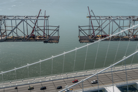
After completing the cut at midspan, demolition crews simultaneously piece away opposing ends of 200m-long cantilevers, working quickly to reduce the unsupported lengths of the antiquated truss.
An additional unique engineering challenge was posed by the eyebars, which were used for those members under significant tension in the bridge service condition. These consisted of between eight and 16 parallel eyebars arranged in packs; they were used in the lower chord at the centre of the suspended span, the upper chords in most of the anchor and cantilever arms, and certain tension diagonals in the anchor and cantilever arms.
It was critical to the stability of the structure that these members remained in tension. For the eyebars in the cantilever arm, tension remained due to the dead weight of the structure throughout the dismantling sequence. However, the eyebar tension in the anchor arm was a function of the weight of the remaining cantilever. As removal of the cantilever progressed, the tension in the anchor arm eyebars decreased and began to approach compression. To prevent the detensioning of the anchor arm eyebars, temporary support towers were installed beneath the anchor arm. When the towers were engaged to the truss, the bridge was jacked to lift up the anchor arm and induce more tension in the eyebars.
Temporary towers were used to support each anchor arm at three positions; the towers used four approximately 1m-diameter pipe columns braced to one other in the transverse and longitudinal direction. One anchor arm was over water and marine foundations were required for the support towers; at these locations pipe piles were driven into the soil beneath the bay. The capacity of these foundations relied on a combination of end bearing and skin friction. Brierley Associates was engaged by Foothills Bridge Co to carry out the geotechnical analysis and determine pile capacity. A pile cap with grouted pipe sleeves was installed at the top of each pile group.
Temporary support bents maintain anchor span stability as the counter-balancing mass of the cantilever is removed.
The other anchor arm was generally over land of varying topography and a variety of temporary support tower foundations was used. The western foundation was over level ground which allowed for the use of a spread footing; the eastern foundation was in the tidal zone and at this location, H-piles were driven to bearing on rock and a tiered-beam pile cap was welded to the top of the piles. The middle foundation was located on rock on a relatively steep slope and the temporary tower foundations used in the original bridge erection were still intact. These consisted of two reinforced concrete pedestals on benches that had been cut in the rock. One of the foundations was carefully demolished so as to determine its load capacity. Based on this investigation, the remaining foundation was deemed adequate for the temporary support tower loads, and the foundation that had been demolished was replaced with a similar design.
As dismantling of the truss approached the main piers, the temporary towers alone were not sufficient to maintain tension in the anchor arm eyebars. In order to maintain the stability of the structure, temporary truss members were installed to create an alternative load path. After installation of the anchor arm temporary truss members, the anchor arm upper chord eyebars were no longer required and could be removed or allowed to buckle.
Throughout the dismantling sequence, surveys were used to monitor the bridge displacement and the data was compared to the predictions of the finite element model. This allowed engineers to verify that the bridge was behaving as expected. Throughout the sequence, the field data validated the predictions of the model, providing confidence in the dismantling plan.
In addition to providing support for the contractor’s operation, an engineer from Foothills Bridge Co was present on site throughout the bridge dismantling and verified the stability of the structure each day. Visual observation of critical members, most notably the tension-only eyebar packs, was used to confirm that the truss was behaving as predicted.
As of January 2015, the dismantling of the San Francisco-Oakland Bay Bridge cantilever spans is ongoing. Many of the key technical milestones have been successfully completed, and the daily removal of truss steel is slowly erasing the iconic profile from the Bay Area skyline. To date, approximately 420m of the cantilever spans has been successfully removed, amounting to 11,500t of the total 21,000t of steel to be removed.
Dismantling of the western portion of the bridge has moved into the anchor span, and the dismantling of the eastern portion is approaching the interior pier. The removal of the cantilever truss spans is scheduled to be completed in the autumn of 2015, with future contracts completing the removal of the remaining spans, piers, and marine foundations.
Nathan Miller and John Walker are bridge engineers and J Coleman is senior bridge engineer at Foothills Bridge Co.