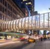
Pedestrians entering Spain's 2008 Exposition will cross a dramatic new bridges which is designed as a building and footbridge combined. Helena Russell reports
When is a bridge not a bridge? When it's an Expo pavilion of course! Visitors to this year's international exposition in Zaragosa in north east Spain will enter the site through a 'living bridge' that is currently being built.
With the last delicate manoeuvre of a major launch now complete, engineers building the new Pavilion Bridge in Zaragoza are racing against the clock to get the structure finished before the Expo opens in June.
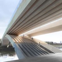
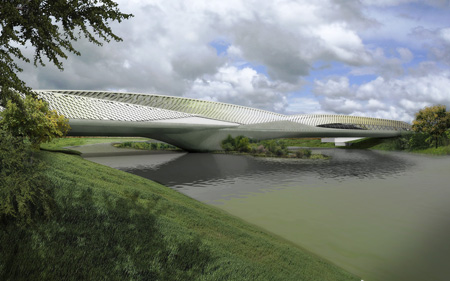
The dramatic structure, which was designed by architect Zaha Hadid and was the winning entry in a design competition, is being constructed over the River Ebro, and will be the main entrance to the site for pedestrians travelling from the city centre. It is curved on plan, a total 260m long, and consists of four steel 'pods' which intersect with one another to provide interior spaces that vary across the length of the bridge.
The concept was inspired by the buds of a gladioli flower, in terms of the shape of the pods and the way they interlock. The bridge has two spans, with an intermediate support on an small island in the middle of the Ebro.
Pod four is the longest of the main elements of the bridge, and forms the entrance from to the bridge; it crosses the Ebro to the central support, at which point it splits into pods one, two and three which offer a variety of different routes and levels via which pedestrians can cross the second part of the river and enter the Expo site, or access a viewing platform overlooking the river and the site.
Essentially the bridge is really a building that happens to be crossing the water; it will have windows, cladding, a fit-out of the interior and building services such as air conditioning and so on. But tight constraints on construction in the river, and the urgency of the programme have led to use of some very unusual building techniques. The easiest way to build the bridge would have been to use temporary supports in the river, but this was not possible because there were tight restrictions on how much of the water flow could be blocked, and for what length of time.
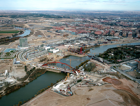
The solution was a compromise - the three interlinked pods on the Expo side of the river would be built in position on a temporary island, and the single, longest pod on the city side would be built offline and then launched across the river into its permanent resting place.
But this was easier said than done, explains Hugo Corres, who is president of structural engineer Fhecor. His firm is the engineering consultant responsible for the detailed design of the bridge, working with the technical department of main contractor Dragados and launching subcontractor Ale Lastra to develop the construction method.
"The time is very short, and the complexity of the project is enormous," says Corres. "When we won the contract, we were starting the final design and the construction at the same time, The launching process was very difficult because of the curvature of the bridge, and the restrictions of the site. Even establishing the centre of gravity of the structure was difficult," he explains.
At the tender stage it had been more or less accepted that launching the main span would be the best solution, and Ale Lastra had been involved in initial discussions at this stage. When the contract was awarded, Dragados and Fhecor joined forces with Ale Lastra to work out the details of how the process should be applied.
"We made a new proposal in just one month," says Corres, "which was a very difficult and complicated process." Dragados technical director Angel Ortega concurs: "We have had to use a lot of temporary elements for support of the structure, and for the launching procedure, to counteract the stresses in the bridge as it is moved." The irregular and curvaceous shape of the bridge, which changes cross-section along its whole length, also added to the difficulties.
Each of the four pods is roughly diamond-shaped in cross-section, with the triangular upper half housing the public areas of the bridge, and the lower half of the diamond below the bridge 'deck', housing the services, maintenance walkway and main structural girders.
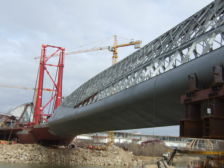
The bridge can be divided into a total of 76 elements, each with upper ribs and lower box girder deck forming a slightly different diamond cross-section. On each pod, the ribs are connected by an arched top chord which runs along the length of the pod and splits into two legs at each end where it connects down to the box girder of the deck. There is no typical section, says Corres, explaining that all the drawings had to be made in three dimensions, and that fabrication of the steel for the bridge is still under way. "We are still working on some of the details," he says. The main steel subcontractor Urssa had to work with ten subconsultants as well as using its own in-house expertise to develop the fabrication drawings and work out how the structure was going to be built.
One of the major difficulties of building the bridge was the architect's insistence that its appearance could not be altered, even down to the spacing and sizing of the steel diagrid that connects the 76 ribs on the upper part of the bridge, and to which the cladding is now being attached. Being able to standardise at least some of the grid elements would have helped with the manufacturing process, but Hadid's practice proved immovable on this issue. The only place that the engineers were able to make changes to the design was below deck, where anything that was not visible from the outside could be altered.
Thankfully, says Ortega, the plans to shotcrete the soffit of the steel structure were abandoned, although not until after numerous test panels had been made, and the first application of the shotcrete had started. It will now simply be painted, a much easier finish for the contractor to apply.
To understand the problems that the team had to solve for the complex launching procedure, it is necessary to have some idea of the structural form of the superstructure, and the constraints of the site. Fhecor civil engineer Javier Andueza explains that there are essentially five structural units that make up the bridge; the top chord, the plates of the bottom deck, the ribs, the diaphragms of the bottom deck and the diagrid which connects the ribs on the inclined, longitudinal faces of the pavilion structure.
The fact that there is no typical section across the whole length of the bridge was an obstacle in calculating the centre of gravity of pod one, explains Corres. His team had to write an application linked to the 3D computer model in order to calculate it correctly so that they could plan the launch of the pod correctly. The influence that the pod's irregular shape has on the centre of gravity can be clearly seen in photographs showing the rear anchors of the launching system. An additional steel girder had to be designed and fixed to the rear of the pod so that the anchors could be connected at the right point - several metres from the centre of the rear section.
The physical constraints of the site also meant that the launching procedure was more onerous than it should have been. A military base borders on to the construction site, and there was no chance that any land could be taken for the launching process. As a result, instead of simply launching the pod forwards to the river, the process had to be split into three main stages - a launch forward, a translation towards the site boundary and another launch forward. In total the launching process incorporated some 20 different stages, with temporary works having to be rebuilt and reinstalled for each stage, particularly in respect to the pod's supports.
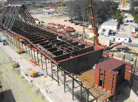
The first phase of construction for pod one was to set up an assembly yard on the bank of the river, with a series of jigs on which the steel sections could be welded together. Once the structure was ready to be moved, it was launched towards the river by about 27m using four jacks, each with a capacity of 500t, and then raised up onto fixed supports once more. The jacking equipment had to be turned by 90 degrees so that the translation process, which involved moving the pod some 9m towards the military base, could be carried out.
With the pod on fixed supports once more, the jacks were once more repositioned, and the final forward-launching process could begin. Two jacks of 500t capacity were used to restrain the pod, via anchor cables. This had to be carried out in a number of stages, with the temporary supports under the structure having to be altered and readjusted every time, because of the changing cross-section and curvature of the pod.
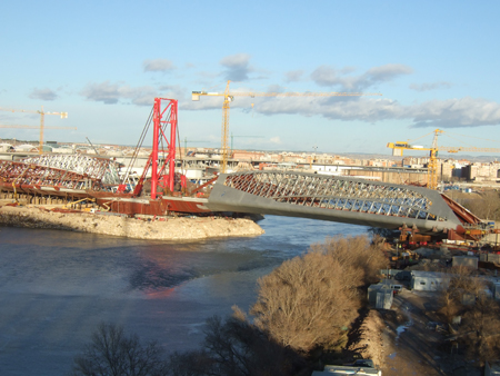
During the early stages of the launch, the pod was moved using solely the jacks, but when it began the journey along its final alignment, it could then be 'fished' over the river using cables attached to a temporary tower at the central pier.
This was a substantial structure in its own right and was custom-designed and built specifically for this project. It consisted of a two-legged steel tower some 40m high which was connected to the upper deck of the permanent structure over the pier. It was tied back from the top of its towers by four, 500t capacity jacks connected to temporary cables, and had two cables connected from the top of the towers to the front of pod one, each with a jack of 850t capacity. The tower also had provisional support via temporary props on the rear side, which were used during erection of the tower, and which could also be used to adjust the position of the towers during launching, when a displacement of maximum 10cm was permitted.
The cables were only used to 'fish' the pod across the river towards the end of the process, when the cantilever had become so long it needed additional support and control. A temporary launching nose on the front of pod one enabled the cables to be connected in the appropriate position for pulling.
When the pod was only a few metres from its final longitudinal alignment, a tricky final procedure was needed to position it for welding the connection with the second section of the bridge. The tip of the launching nose was lowered onto a temporary support on the front of the second section, so that the cables could be disconnected from the launching nose and reconnected to pod one. The weight of pod one could then be transferred back to the cables, and the launching nose and temporary support removed. Connection of a new temporary support to the top of pod one enabled it to be lowered the final 2.7m to rest on the other half of the bridge, at the correct elevation but with a gap of just 500mm between the two.
The missing piece will be fabricated once a full survey of the gap has been carried out, to ensure a good fit, explains Andueza. When Bd&e visited the site in late January, preparations were being made for the last two stages of the launch process, with Ale Lastra under pressure to finish the work and dismantle its equipment in record time. "We are hoping it will take just one or two weeks to remove the tower and the temporary works," says Ortega. "Normally this could take anything up to a month, but it is on the critical path and we need it removed as quickly as possible." Erection of the remainder of the superstructure cannot start until the temporary works has been removed from the deck.
Time is certainly of the essence, with the Expo due to open in June, and still some 25% of the superstructure remaining to be erected. But the team is no stranger to short programmes - the contract only began in July 2006, and the first pieces of steel were delivered to the site in January the following year. The amount of progress that has been achieved in just one year is quite impressive, so it is not difficult to believe the team can still meet the schedule.
With all the attention focussed on the difficulties of the launch, it is easy to forget the challenges of the second span of the bridge. These have mostly been fabrication and erection problems, with the three interlocking pods creating some very demanding details for the steel fabricators. At some points where the pods interlock and the legs of the top chord meet the deck, the junctions were extremely difficult to detail and fabricate, Andueza explains.
Starting out
In the early stages of the project, consultant Arup was appointed to carry out the detailed design up to tender stage, and associate Duncan Steel explains that this was based on previous collaborations between Arup and Zaha Hadid. But the process was rather different to a traditional bridge design, Steel says. “Essentially we had to design a building, and we also had to make it work as a bridge,” he recalls.
In Zaragosa the climate varies from very hot in the summer to very cold in the winter, so the designers also had to also consider aspects such as air conditioning and climate control, something alien to the usual procedure of bridge design.
The concept design by Zaha Hadid Architects basically came as an outline, says Steel, in the form of a 3D model created in Rhino modelling software. “It was a very complex shape and our aim was to turn it into something buildable,” he explains. But naturally it was not such a straightforward process – while the structural engineer’s instinct is to attempt to simplify the structure, the architect wants to retain the original vision and not let it get watered down.
“We tried to develop repetition within the elements to some extent,” says Steel, “in order to try to keep within the cost limitations”. Not only was a budget set, there was also the issue of the fixed deadline – the structure must be ready for the start of the Expo later this year. Hence it was vital that the structure should be as buildable as possible, so its construction did not fall behind schedule.
The shape of the concept design was very fluid, curved in plan and with a cross-section that varies along the length of the whole bridge, due to changes in the height of the roof, and the intersection of the various pods. Hence the first thing Steel and his colleagues had to do was try to impose some kind of order on the structure, by making all the ribs parallel. This made it possible to create cross-sections throughout the length of the bridge, and draw them in a single plane, simplifying things considerably for the structural engineers.
The conception of the structural form also changed in the design process, explains Steel. While the architects had conceived the pavilion as an arch bridge, it was so stiff that it did not really act in this way, he says, and the team had to try and rationalise its behaviour.
The façade engineering played a part in this – the concept design included a lot of diagonal elements connecting the main ribs, but these were initially included as a means of connecting the façade to the ribs. “We decided to use these as bracing,” explains Steel. Using the OASYS structural analysis programme GSA, engineers imported some 30,000 elements and many thousands of nodes from the model, but the software was able to analyse it very quickly.
Parametric studies revealed that the bracing created a very stiff structure, which essentially acted as a truss but with some of the load still coming down through the arch elements.
“We then tried to group the elements into similar bundles for purposes of creating repetition and enhancing its buildability,” says Steel. Sizes were optimised for each group, rather than individually, with worst-case conditions being analysed in the same way. It was not the most sophisticated solution, but it allowed the tonnage of steel to be calculated for QS purposes.