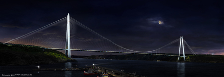
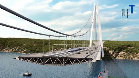
In little over a year’s time, the thousands of trucks that queue daily to cross the two bridges over the Bosphorus Straits in Turkey will finally have an alternative, with the opening of the Yavuz Sultan Selim Bridge which will cross the straits at its most northerly point. This new bridge with its 1,408m-long main span is not only notable as a much-needed congestion reliever, but will be the first time a hybrid system of cable support has been used on such a large scale. It will be the longest combined road and rail deck, has towers reaching 320m in height, and its almost 60m-wide deck also puts it among the world’s largest.
As the only shipping passage from the Black Sea to the Aegean and beyond, the Bosphorus Straits have huge strategic significance for Turkey. All commercial and military traffic to and from Russia’s Black Sea ports has to travel through it, and it is the only access from the seabords of Ukraine, Bulgaria, Georgia and Romania to the world’s oceans.
But while Turkey gains from its position on this strategic seaway, it also suffers from the fact that it is a barrier to trade, and prevents easy movement of goods from the Asian land mass to European markets. Currently highway traffic only has two routes by which to cross the Bosphorus; not only are these two bridges heavily congested for large periods of the day, the routes leading to them also suffer. With road improvements in the offing or already being constructed in the most easterly parts of the European Union, Turkish manufacturers want to have the opportunity to export their goods more cheaply and quickly and this can only happen if links across the Bosphorus are improved.
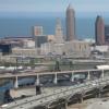
The Third Bosphorus Bridge – its official title being the Yavuz Sultan Selim Bridge – is located at the most northerly extreme of the straits with the intention that it will allow through traffic to bypass the congested roads of Istanbul’s main conurbation. Since this part of the country is largely undeveloped, the project also requires construction of many kilometres of new roads, to create the Northern Marmara Motorway, and this has not been without controversy, with environmentalists raising oncerns about the destruction of habitats along the route.
In order to fund such a major project, the Turkish government chose to go down the private finance route, although initially this was not an entirely straightforward process. The Turkish Ministry of Transport, or KGM, initially launched a competition for a private finance partner to bid on 350km of new motorway and a new crossing of the Bosphorus. But the size of this undertaking proved difficult to finance, and the invitation went unanswered.
In response, the government came back with a revised project, relaunching the scheme and cutting back the highway undertaking to just 70km. Crucially, they also offered a minimum traffic guarantee for the repayment model – a generous one, and one which could not help but pique the interest of potential bidders.
Tenders were invited at the end of February 2012, with consortia being given just five weeks within which to compile their bids. T-Engineering project engineer and director of the design team Jean-Francois Klein recalls it clearly: “We had no geotechnical information, no seismic information, wind data or anything – it was very tricky!” The deadline was extended by a few weeks, he says, but it was still a demanding schedule. Nevertheless, five or six teams submitted bids.
Klein and Michel Virlogeux were invited to partner with the Turkish-Italian group ICA, a consortium of IC Ictas Construction and Astaldi, to bid for the job. Virlogeux had previously worked with Astaldi and this was how the connection was initially made.
The timescale for submitting the initial bids was tough, but as Klein explains, this was only a flavour of the challenge that lay ahead. KGM set down four strict criteria for the bridge design, which bidders were obliged to address.
The first requirement was that it should be a suspension bridge, to match with the two existing bridges across the Bosphorus, and the second was that its appearance should be in line with the architecture of these bridges, both of which have streamlined orthotropic box girder decks. So far, so simple. But it was the addition of the third requirement that put the screws on the designers – it must not only carry four highway lanes in each direction, it also had to accommodate two railway lines.
As if this wasn’t enough, smiles Klein, the KGM had a fourth requirement – that it had to be completed within 36 months. Not a 36-month build period, however; a 36-month start-to-finish including financing, design studies and testing, data collection and so on.
Completion of the bridge, which began construction in March 2013 is currently expected to take place next summer – an incredible feat if they pull it off. In financial terms it is around a third of the contract value for the concessionnaire – some US$805 million of the total US$2.8 billion.
Aside from the four main criteria for the bridge design, the client also specified a minimum span of 1,275m for navigational purposes. The Bosphorus, which is used by some of the world’s largest vessels, is notoriously difficult for them to navigate. So much so that access for large vessels has been restricted to one-way for almost a decade now, with ships sailing through in one direction for 12 hours a day with the direction reversed for the following 12 hours.
But even with this restriction, a significant span was demanded by KGM. Klein recalls that the first decision he and Virlogeux took was that they should make this span even larger – a suggestion that took some effort to ‘sell’ to their contracting partners.
The logic was simple – by adding another couple of hundred metres to the span, the foundations of the main towers could be built on land. Given the fact that there was no geotechnical information provided, on which to make an informed decision, they instead decided to make a guess, largely based on experience, that conditions on land would be better than in the water. “We supposed that there would be better ground conditions, and that this would give the consortium a stronger chance of meeting the schedule,” Klein says. “We really didn’t want to go offshore with the towers, which is what would have happened if we’d stuck to the minimum span requirement. In fact this proved to be the most important and best decision of all those we took on the project!” As well as minimising construction risk for the consortium, this adaptation also offered benefits in terms of less risk to shipping – an important consideration in the busy Bosphorus Straits – no impact on the water flow, fishing grounds or water quality of the straits, and no risk of pollution during construction of the tower foundations.
It did take some effort to convince the contractors, says Klein, but they managed to do so and once construction began, the decision immediately paid off.
However the room for manoeuvre as regards other aspects of the alignment was minimal. A longitudinal alignment of around 100m wide was allocated for the crossing of the Bosphorus, offering little opportunity to adjust its position otherwise.
But while the decision to make the main span longer was to have a beneficial impact on the programme, it introduced greater complications in terms of the structural behaviour of the bridge, particularly for the railway loading.
This was always going to be a difficult issue to resolve, admits Klein, given that the usual solution on long-span suspension bridges would be to adopt a traditional truss for the deck, which would provide the necessary stiffness to the main span. But such a solution would not only have gone against the designers’ wishes to create an elegant bridge, the owner’s demand that the bridge have similar aesthetic characteristics to the existing crossings also eliminated this possible solution. Klein says: “For this kind of bridge you would need a truss up to 17m deep. Not only would this have made the abutments complex, we didn’t really think it would fit with the spirit of the requirement to match the spirit of the other two bridges.”
He and Virlogeux quickly concluded that the only solution was to put all the traffic on a single level – as a consquence this is a very wide bridge, almost 60m in total. From an aerodynamic point of view, it is possible to work with a very streamlined box girder, but as far as deflections under live load are concerned, the stiffness that a truss would offer is absent.
“As a result we had to come up with other ways of improving the global stiffness of the bridge,” says Klein, “and we did this by working with the cable system.”
The outcome is the creation of what has been dubbed a ‘high rigidity suspension bridge’ – politically it seems necessary to refer to it as a suspension bridge, rather than a cable-stayed bridge, to meet the aspiration of identification with the existing crossings. And indeed it could be considered as a suspension bridge as it has most of the hallmarks; main cables, cable anchorages, saddles and so on – the main difference being that the hangers are restricted to the central part of the main span.
A system of stiffening cables – identical to traditional cable stays – is used to support the deck units closest to the towers, and the combination of the two systems creates three distinct zones of cable support. The stiffening zone describes the area of deck either side of the main towers that is supported solely by the cable stays; the suspended zone is the area across the mid-span where the deck is supported solely by hangers from the main cable, and the transition zone is the area in between where both hangers and cable stays are in use. The suspended zone covers a length of 312m, the transition zone around 216m and the stiffening zone around 332m. Of course it is not a new solution – the Brooklyn Bridge being a notable example – but it is by far the largest application.
This hybrid cable system was really the only solution for keeping the traffic all on a single deck, but subsequent comparisons with a traditional double-deck truss suspension bridge of the same size show that it not only requires significantly less material, it also deflects much less. Vertical displacement of 3.75m under maximum loads on the high-rigidity suspension bridge compares with an equivalent of 9m on the traditional suspension bridge, and while other differences are not so dramatic, they are still lower in all cases.
The main suspension cable remains in the same vertical plane across the full length of the bridge – it is connected to anchor blocks behind each abutment, and runs over saddles on the top of the A-shaped towers.
The two cables are much closer together than they would be on a traditional suspension bridge, where the hangers are generally connected to the outer edges of the box girder deck. In this case they are connected to the deck along the edge of the central portion of the deck which carries the railway, and are just 13m apart. The stiffening cables, meanwhile, are anchored to the tower top and then splay to anchors along the edge of the box girder at deck level.
The deck cross-section is designed to carry a pedestrian footway on each side (although these are only for maintenance access, they will not be open to the public); four highway lanes on each side, and two railway lines in the middle of the deck. At 58.5m it is an exceptionally wide deck for such a long span – by comparison the 1,104m-long main span Russky Bridge has a deck only half the width, and only the deck of Stonecutters Bridge, at 53m wide, comes anywhere close.
Suspension bridge decks are even narrower in general – Akashi Kaikyo has a main span some 500m longer, but its truss deck is only 36m wide. Runyang in China has a comparable span but its deck still only reaches a width of 45m.
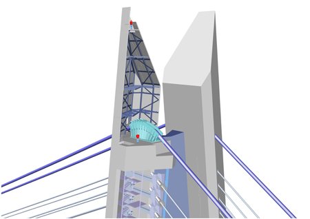
The main towers of the Third Bosphorus are A-shaped, with a cross-beam below deck level, and a further connection at the top of their 320m height. Their inclined legs have a triangular cross-section with chamfered corners; this design not only improves the stability of the towers, it also contributes positively to the aesthetics of the structure although as Klein points out, it adds complications in terms of the formwork required, as it changes from one pour to the next.
The scheme was originally bid with steel towers as well as a steel box girder for the deck of the main span – in effect to play it safe in the absence of any seismic data. But subsequently, when the data was fully analysed, the potential seismic loads turned out to be relatively low and they were able to revise the towers to make them concrete. This is much better in terms of the local expertise in concrete construction, as well as economically favourable, says Klein.
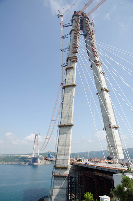
The height of the towers above the ground level is greatest on the European side of the straits, reaching a height of almost 322m, and they are almost 330m above water level.
Klein explains that it was particularly crucial to define appropriate live loads for the structure – while the client might be tempted to ask for additional capacity to allow for future increases in traffic, this could have undesirable consequences for the stiffening cables. The longer cables – those of 600m length and greater – would be liable to be totally unloaded when the bridge was only carrying dead load, making them sag, and putting them at risk of fatigue damage. It is necessary to avoid over-estimating live loads to reduce these drawbacks and to emphasise the structural efficiency of the bridge, using a realistic approach. With this in mind, the specified design loads are permanent loads of 470kN/ml and 250.84kN/ml of distributed loads – a ratio of 0.54. The allowable stress was increased to 50% of guaranteed ultimate tensile stress, and strands of 1,960MPa capacity were specified.
The main suspension cable is unusual in that it will only be loaded over its central portion, so it is only in this zone that it will take a catenary form. Also, the cable will have a larger diameter in the back spans than in the main span, with an additional nine bundles of PPWS strand being anchored onto the saddles at the top of the towers, making a total of 122 bundles in the back span and 113 in the main span.
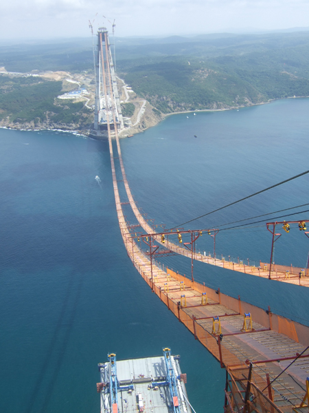
The hybrid form and partially-loaded main cable, combined with the very stiff tower legs, also impact on the construction process, with the saddles having to be moved during the process of installing the hangers to prevent the cable from slipping in the tower saddle. When Bd&e visited the site, the first of the four huge tower saddles had just been installed – a complex process which involved raising it by strand-jacking between the two inclined legs to the top of the 320m-high tower, and then moving it transversely by a metre or so to the correct position for the cable erection. Once the cable is erected, and as the hangers are installed, the saddles will be moved again by some 2.7m to their final position. The top of the towers is currently home to a significant amount of temporary equipment and large lifting frames for the saddle and cable erection; all of these will have to be dismantled and lowered back to ground level once the cables are complete.
The engineers analysed a lot of different options for the erection of the main cable hangers – the idea of starting at the centre of the span and working outwards had to be discounted because the two cables are so close together. As a result the team intends to erect all the segments which have stiffening cables first – up to segment 21 – and then they will erect the hangers over the transition zone which covers segments 12 to 21. This will stabilise the main cable so that they can then install the hangers in the suspended zone as the deck units are lifted.
There are 22 stiffening cables on each side of the main span deck at each tower, and the same on the back span deck – a total of 88 at each tower. The system also has 34 hangers per main cable over the central section of the span, making 68 in total. Guarding against sag of the longer stiffening cables was again a concern in the distribution of forces over the transition zone. “We need sufficient load in the last stiffening cables to prevent them from sagging,” Klein explains, and says that the ratio is about 70 to 30 between the hanger and the stiffening cable.
The back spans of the bridge are made of concrete and the main span of steel – the joint between the two is just 24m into the main span from the tower axis creating a concrete deck length of just 308m. The deck was built in situ on a huge forest of falsework, and has the same cross-section as the steel deck for continuity purposes.
In the back spans, the stiffening cables are anchored into the concrete deck along the boundary between the railway line and highway lanes, creating an interesting visual effect as they converge inwards rather than splaying outwards as they do in the main span. They are also anchored much more closely together, at 15m spaces rather than the 24m spacing of the main span.
Pendular bearings have been selected in order to control longitudinal displacements and seismic behaviour of the bridge, and these are installed on the tower cross-beams below the deck, as well as at the back-span supports. They have been designed to optimise temperature effects, the effect of a train stopping on the bridge, the dynamic loads from trains, and the earthquake loads.
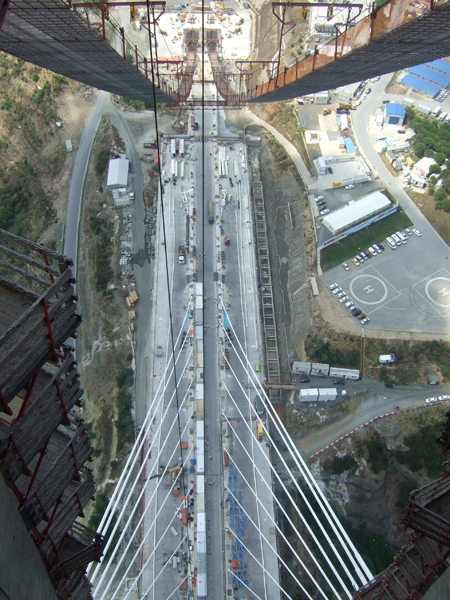
When construction kicked off in March 2013 – by subcontractor Hyundai – the benefits of expanding the main span became obvious immediately. “The foundations were just 15m from the water of the straits,” says Klein, “and we found good, dry rock which was perfect for construction.” At the same time the contractor built a temporary platform at the edge of the straits which could be used for delivery of the first steel deck segment, and for storage of materials since there is very little space available at the site.
With the foundations safely completed, tower construction began in July 2013. The designers’ proposal for construction was that the towers should be built concurrently with the erection of the deck units, but the contractor decided to simply proceed with the tower construction to full height. Consequently the towers reached full height in November last year – Klein admits to a few sleepless nights during this period, considering that wind speeds at the site can reach more than 150km/h on occasion.
Cable anchorage boxes in the tower – which start at a height of 208m, were made particularly complex by the changing geometry of the inclined legs and the angle of splay of each stiffening cable.
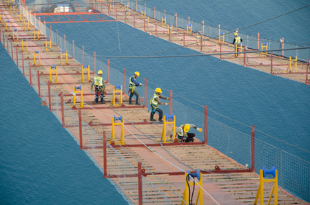
Once the concrete box girder deck had been built in situ, construction of the steel deck kicked off in earnest, with the first steel unit being lifted on 25 December last year. This element was only 4.5m long – being the transition unit it was extensively stiffened and much heavier than the standard elements. Also it had to be handled on land for erection, rather than being lifted directly from a barge like the subsequent elements.
Steel plate from South Korea is being used for the main span, fabricated and assembled by a group of Turkish shipyards on the Black Sea. Quality was an issue to begin with, says Klein, but a revision of quality assurance procedures and more stringent oversight by the contractor seems to have improved matters. However with the proximity of the fabricators, delivery of deck units takes just a day – with no storage at site, this is an invaluable benefit.
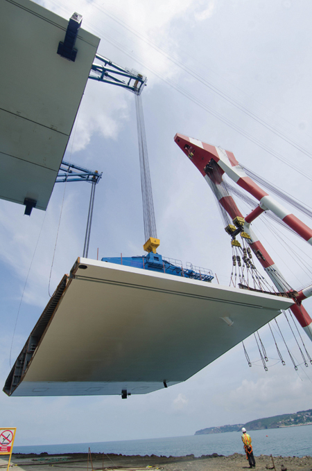
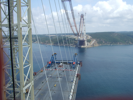
When Bd&e visited the site at the end of last month (July 2015), the tenth deck unit had just been lifted on the European side, and welding and cable erection was in full swing. The team is now working to a turnaround of about eight days per deck unit, and the progress on the Asian side of the straits, which is being carried out by a separate team, is following on with just a few days’ difference in schedule. The size of the deck elements – at almost 60m wide and 24m long and weighing almost 900t – makes matching to the previously-erected segment a delicate task. The positions of the two lifting derricks – designed and manfactured by NRS – as well as the positions of the lifting hooks and ancillary equipment – is all specified by the bridge designers to simplify the joining process as much as possible.
Closure of the deck is anticipated for the end of the year or early 2016 – at the moment the main item on the critical path is cable erection, which is reported to have been held up by quality issues with the tower saddles. The first delivery of saddles, which the contractor ordered from a Chinese firm, had to be rejected due to problems with material quality, and new saddles had to be ordered from an Italian manufacturer. Catwalks are ready for cable erection to begin once the tower saddles and anchor splay saddles are in place.
Even once the deck is closed, another six months or so of work will remain, including the installation of dehumidification systems in the main cable, anchor chambers, steel deck and tower tops.
Owner: KGM (Turkish Highways Authority)
Concessionnaire: IC Ictas – Astaldi consortium
Conceptual bridge design: Michel Virlogeux and T-Engineering
Detailed bridge design: T-Engineering, Greisch
Independent design control: Setec
Lender’s technical adviser: Mott MacDonald
Bridge EPC subcontractor: Hyundai Engineering & Construction, SK E&C
Stiffening cable supplier: Freyssinet