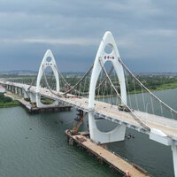
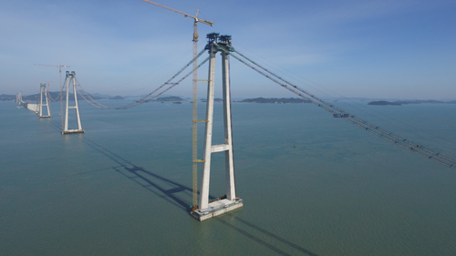
Saecheonnyeon Bridge — or New Millennium Bridge — is the first multi-span suspension bridge in Korea. It has three concrete towers and four steel spans and will form part of a new 10.8km link connecting the islands of Aphae and Amtae across the main navigation channel near Sinan-gun, Jeollanam-do, in the southwest.
The characteristics of 21st century bridge technology can be summarised in two keywords; elongation and enlargement. These have made it possible to construct suspension bridges capable of crossing major bodies of water such as sea straits.
These long-span bridges require construction techniques that can provide plenty of navigation space to accommodate the logistics requirements of shipping. However, it is difficult to efficiently and economically overcome certain constraints faced by by the use of girder bridges at such crossings, for example excessive water depth and poor ground conditions. As a practical solution to this problem, multi-span suspension bridge construction techniques are becoming increasingly attractive as the next-generation of suspension bridge technology.
The 1,750m-long bridge is a triple-tower suspension bridge with four spans and a deck consisting of a single steel box girder that will carry two traffic lanes. The main cables are anchored in concrete anchorages founded on bored piles by reverse circulation drilling and steel open caissons. At the main span, hanger ropes with a diameter of 75mm and a cross-section of CFRC, a proprietary cable hanger system produced by Kiswire, support the steel girder.
Construction of the project began in November 2010, with the foundation installation and concrete work for anchorages and the tower continuing until March 2017. Preparation work for cable erection including the installation of temporary structures, saddles, catwalk system, hauling system and erection machine system took six months to carry out, after which PPWS cable erection work took 40 days to complete from the end of June to early August. The erection of the steel box-girder deck began in the last week of October last year and was completed in the first week of January.
As cable-supported bridge spans get longer, an increase in the size of each structural element is inevitable, leading to various structural challenges.
In the case of the deck box girder, the cross-sectional structure needs to be strengthened to ensure it retains sufficient stiffness in the horizontal plane and can resist torsional movements. For cables, considering the tension is proportional to the square of the span of the bridge, any elongation of the span requires an increase in cable cross-section, subsequently this leads to an increase in self-weight, and a consequent extension of the tower height.
As an alternative to overcome these problems, multi-span suspension bridges have three advantages. It is possible to optimise the central span design; they have improved wind load stability; and the anchorages can be reduced in size. The design of the New Millennium Bridge was carried out so that it could benefit from all these advantages.
The main cables have a diameter of 300mm and consist of 21 strands, each of which contains 127 wires, making a total of 2,667 wires per cable. And the 5.3mm-diameter wire has a high tensile strength of 1,960MPa. The cables were installed as prefabricated parallel wire strand and the total weight of the two cables is 1,847t.
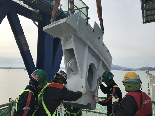
In order to eliminate the requirement for a temporary structure capable of heavy lifting, the cable saddle was designed as a hybrid element with a concrete base and a steel upper section, fixed using shear studs. This type of saddle was first used on the Askøy Bridge in Norway and has major advantages in terms of practicality and economics.
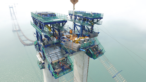
In multi-span suspension bridges, it is necessary to consider how the vertical displacement of the main span, which is caused by the longitudinal displacement of the centre tower, can be controlled. In the case of the New Millennium Bridge, an H-shaped tower was designed in order to increase the stiffness of the main tower, and the vertical displacement of the main shaft was controlled by making the central tower larger than the two outer towers.
The multi-span suspension bridge is 1,750m long and the two central main spans are each 650m long, with two side spans of 225m each. There is a difference in height between the three towers, with the tower in the centre being almost 168m high and the two outer towers shorter at 155m. Main cables are connected to anchor blocks which are built in the water.
The cross-section of the girder had to be designed with a focus on ensuring aerodynamic stability while reducing the self-weight of the deck. According to a study by steel fabricator Kubo Industries, it was suggested that a separation interference angle of 30° and lower plate slope of 13° would be the optimal section for securing the aerodynamic stability of the girder.
As regards aerodynamic design, wind-tunnel tests were carried out on both a sectional model and a full 3D model of the bridge, in addition to the theoretical analysis. The basic wind speed (V10) with a 200-year return period - design life of 100 years and non-exceeding probability of 60% - was established at 34.7m/s through statistical analysis of the long-term data recorded at Mokpo weather station.
A design wind of 69.8m/s was evaluated to investigate the flutter of the whole structure. The 2D section model test, which was scaled to 1/50, confirmed that the flutter wind speed exceeded 100m/s and torsional vibration induced by vortex shedding was not generated by turbulent flow. In the 3D model test scaled to 1/180, flutter and vortex shedding didn’t occur even in the construction stage.
The anchorage enabled span lengths to be reduced in comparison to short-span suspension bridges, so it was possible to relatively reduce the horizontal component force transmitted to the anchorage. The horizontal force acting on the anchorage of a multi-span continuous suspension bridge depends on the length of only one main span. Due to the reduced horizontal cable force, the height of the anchorage is less than 20m and the cross-section of rectangular caisson is 32m by 21.6m. Since the sediment layer is deep at the installation location, it was necessary to select a foundation type that was practical and stable. Bored piles and steel caisson type foundations were applied at the anchorage.
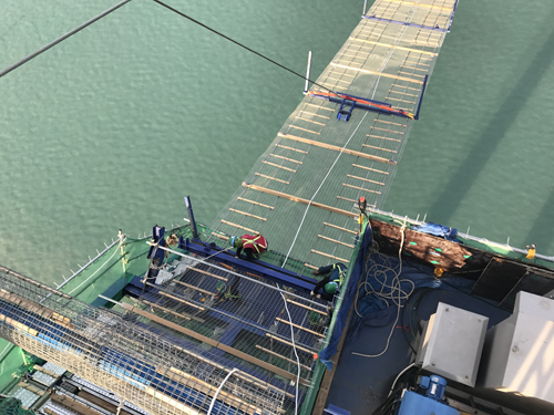
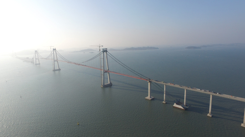
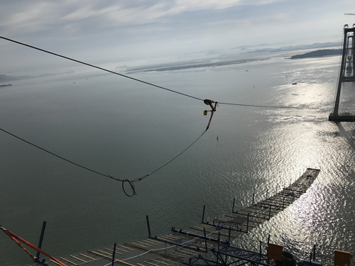
The catwalk system that is used in construction of a suspension bridge is a temporary structure that is connected to the anchorages at both sides. It enables workers to access all areas where cable-construction related procedures are taking place, including erection, compaction, wrapping and so on.
The catwalk system for this bridge was supported by six wire ropes each with a diameter of 31.5mm, creating a 4.2m-wide by 6.75m-high cross-section of working area and spanning a total length of 2,065m. These ropes are separated by the centre tower. Gallows frames supporting the hauling system were located at intervals of 42.5m. The catwalk floor was located under the cable with a gap between the main cable and catwalk floor of 1.3m.
To ensure the aerodynamic stability of the catwalk system, 16 cross-bridges were installed at various points. Installation of the catwalk system for this bridge started with the erection of a pilot rope across the straits; this pilot wire rope (φ25) was pulled across by a tug boat in a span-by-span sequence. A hauling system for erecting the catwalk ropes, tramway support ropes and hand ropes was then carried out with the pilot rope. The temporary hauling system was driven by two winches with a capacity of 25t. When the catwalk ropes were being erected across the navigation channel by the hauling rope, their tension had to be controlled in order to prevent the catwalk ropes getting waterlogged and to prevent the hauling rope tension exceeding the driving winch.
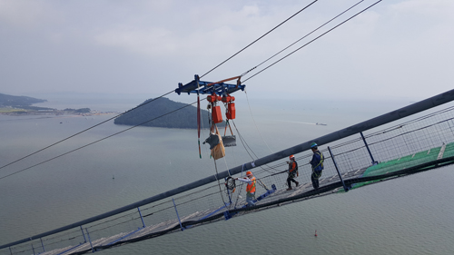
After the erection of catwalk ropes was completed, assembly of the catwalk floor was carried out. In general this consists of wire mesh made of steel wire and wooden elements that act as steps. It is fabricated in advance in a roll at the factory before being brought to the construction site. They were pulled up towards the tower using the tower-top winch from the anchorages. From the top of the tower, the floor rolls were unrolled down towards the centre of the main span under the power of gravity.
Cross-bridges were installed at various points of the catwalk spans; during unrolling work, they were lifted using the tower crane and connected to the floor at specific locations that had been marked out.
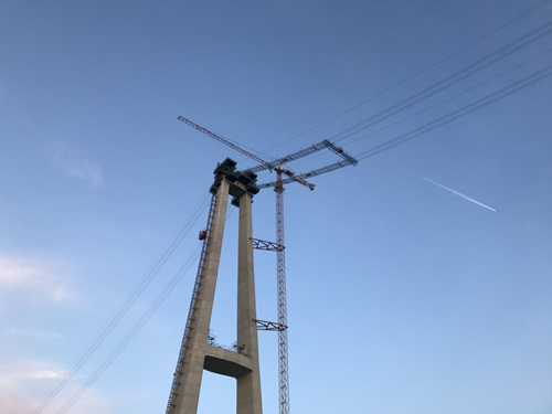
Generally, in suspension bridges, the process of installing the cable saddle on the top of the tower is one of the most dangerous and notable stages, as the tower saddle is usually the biggest and heaviest structural element. To reduce the potential hazard from this procedure, a hybrid type of saddle with a concrete base and steel upper section was designed for the New Millennium Bridge. With this adaptation, the weight of the element that had to be lifted by tower crane was only 3t, and this could be raised using the cranes that had already been erected for the tower construction. This eliminated the need install any temporary equipment for this procedure and hence has advantages in terms of construction programme and costs. Concrete’s excellent resistance to compression is another advantage a hybrid saddle can benefit from.
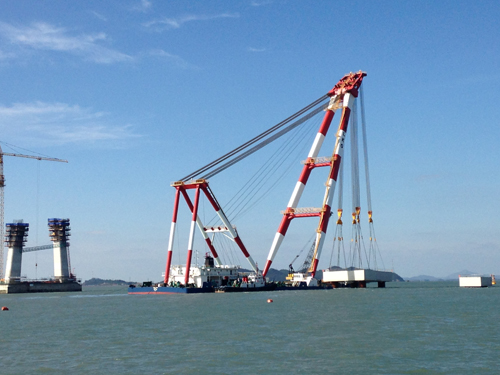
The total weight of the main cable is 1,847t, and the 5.3mm-diameter wire which has a tensile strength of 1,960MPa was manufactured and wound on coils by Kiswire in South Korea. These coils were then relocated to a factory where they were used to make the PPWS cable. One unit of PPWS cable, the full length of all spans, was wound as a type of coil, and a socket for connection to the anchorage was fixed at one end of the cable. These coils were brought to the construction site by a floating barge.
Cable erection work on the New Millennium Bridge was carried out from the last week of June to the first week of August last year. The PPWS erection system included a strand unreeler which was installed behind the anchorage. A hauling system was also installed along each cable line and one rope carrier for each line was used to pull one strand from one anchorage to the other.
One strand consists of 127 wires and each main cable consists of 21 strands. A total of 21 trips was needed to complete one cable, and the total duration of the cable pulling work was 40 days.
Cable geometry survey and adjustment work for the erected strands was carried out. For the sag survey, strand numbers 1, 9 and 19 were used for the absolute measurement, which was carried out by a geodimeter installed at each tower top, and the other strands were adjusted based on relative measurements. The geometry-adjustment work took place overnight, from 10pm to 2am to reduce the impact of temperature on the configuration of the strands as much as possible. To determine the amount of correction of the length of the strand, the average temperature was established by measuring at both sides and the top of the strand.
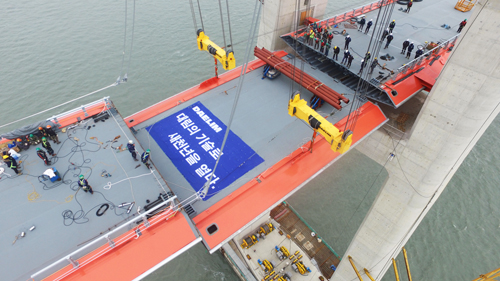
In the initial design, the deck was divided into 85 elements, which were intended to be lifted simultaneously in the four spans, requiring six erection gantries — two for each of the main spans and one for each of the side spans. However, availability of equipment for the deck erection was an issue, as there were not enough lifting devices to enable simultaneous lifting in all four spans. Only four sets of lifting devices were available; these had previously been used for construction of the Yi Sun-sin Bridge and the Jeokguem Bridge. There was not enough budget available to pay for construction of two additional gantries, so the process had to be adapted to make it suitable for limited equipment.
In the revised construction procedure, the deck elements in the main spans were lifted first, after which the gantries were relocated from the main spans to the adjacent side spans. During the time that the gantries were being relocated, those deck elements closest to the towers and at both ends of the bridge were erected by use of a floating crane. The key issue in this plan was the imbalance of the cable forces at the towers, which could cause cable-saddle slip and induce moments at the bottom of the towers. In addition, the large variation of the cable geometry leads to the second stress in the cables. Therefore, structural forces including stress in the towers, cable slip at the saddle and second stress in the cable were checked at every erection step and for every simulation case.
Lessons learned from the deck erection of a previous bridge project prompted changes to the gantry equipment to reduce risks and improve safety. After each deck element is installed, the gantry is pulled to the next lifting location by means of two lines of wire ropes attached to winches on the top of the towers.
Movement of the gantry is accomplished by means of a driving roller which is installed underneath it; the potential for derailment of the gantry arises due to various factors, such as a difference in speed between the two parts, or a slip of the lifting rope. In the case of a derailment, a deck element under erection could collide with those already installed, or in the worst case scenario, both gantry and deck element could fall. As well as the potential risk to life, recovery from such events is time-consuming and expensive.
On previous projects, no device had been provided to prevent or warn of derailment, and gantry operators were being relied upon to report any issues. For this project, a derailment prevention system which combines lateral guide rollers, laser pointer and load cell was devised and implemented to improve safety and minimise risk. The New Millennium Bridge is due to open to traffic in December this year.
Jung-in Kim is a member of the bridge engineering team at Daelim Industrial