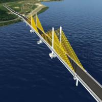
In addition to providing new road capacity across the Yamuna River near New Delhi, the Wazirabad Bridge, which is currently under construction, is intended to create a new landmark for the city. The crossing was commissioned by the Government of Delhi with the intention of creating a structure which would be symbolic of the emerging India. It will be a central element of a new tourist destination that is being created in the north east of the capital, and it is due to open to traffic at the end of 2014.
From a transportation point of view, the new link will offer additional capacity across the Yamuna River in the north of New Delhi, where there is only a two-lane across the Wazirabad barrage. Future plans include widening the area around the bridge to create a new lake as a tourist destination.
Hence the client Delhi Tourism & Transportation Development Corporation wanted a long-span, lightweight design that could have the potential to become a tourist attraction and a landmark for New Delhi. The bridge will also have a state-of-the-art lighting system, an elaborate bridge health monitoring system, internal elevators and an external mechanised cleaning system. A number of design workshops were held with the client, resulting in a structure with novel features that make it an easily-identifiable signature bridge.
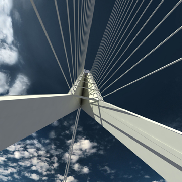
But the design still evolves from well-proven structural solutions including a slender composite deck, for example. This type of bridge deck was used on the first cable-stayed bridge in India, the Second Hooghly Bridge in Kolkata, and has since become common worldwide. The most striking feature of the 675m-long cable-stayed bridge is its inclined, bow-shaped steel tower, the upper section of which is clad in glass. Two cable planes support the 251m-long main span and a single cable plane connects to the backspan; both are anchored in the top of the tower.
The approach by designer Schlaich Bergermann & Partners was to create a bridge with a dynamically-shaped tower, but one which also makes structural sense. The dead weight of the inclined tower partially counter-balances the dead weight of the main span deck, thus reducing the number of backstay cables that are required. The shape of the tower head is designed to enable the forces in the two planes of cables at the front and those in the single backstay plane to be transferred directly.
Applying typical Indian ornamental graphics to the tower top is intended to further enhance the visual impact of the bridge. The tower itself has a large glass-clad head, providing inspection platforms which can also function as viewing platforms and with illumination, convert the tower to a beacon that is visible from afar. Small elevators will be installed into the tower legs to access the platforms.
While other bridges of similar appearance feature inclined masts which widen towards the deck – for example the Alamillo Bridge in Seville and the Erasmus Bridge in Rotterdam – the mast of the Yamuna Bridge is hinged at the bottom, which suits the truss-like behaviour of cable-stayed bridges. Since the resulting force of the backstays enters the tower above the level of the main span cables, the induced moment counteracts the one caused by the change of direction of the tower legs.
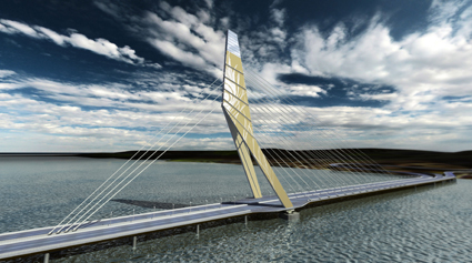
Hence the structure combines robustness and structural sanity with the expectations that come with a signature bridge. Only after the concept was approved by the Delhi Government and the Delhi Urban Arts Commission was the detailed design developed. The composite deck of the bridge is approximately 35m wide and carries two, four-lane carriageways which are separated by a concrete crash barrier as well as two emergency lanes along the cable anchorages.
As a composite structure the deck is formed of welded I-shaped longitudinal main girders along its edges, with I-shaped cross-girders at 4.5m intervals. A central main girder distributes localised wheel loads from heavy trucks onto several cross-girders. Precast deck slabs of concrete grade M50 will span 4.5m between cross-girders, and their standard thickness of 250mm increases to 700mm at the main tower and in the area of the backstay anchorage. Use of this type of deck not only enables the steel grid to be quickly and efficiently erected, but it also offers the advantage that the concrete counterbalances the horizontal cable thrust, offering cost-free prestressing.
The deck is longitudinally restrained at the tower only, hence the longitudinal movements at the ends of the bridge due to temperature can be up to 250mm in both directions. State of the art expansion joints will be used at both ends to connect to the adjacent structures. The deck is supported by two cable planes, the dead ends of which are anchored directly to the webs of the outer main girders at 13.5m centres. The cables are formed of between 55 and 123 parallel strands, depending on their location, and the strands will be stressed from chambers at the top of the tower.
Corrosion protection will consist of the use of hot dip galvanised wires and individually coated strands that are covered by an outer PE-pipe. In the back-stay area, the lower part of the cables will have fire protection. The two legs of the tower are made of welded steel boxes which merge into a single upper tower zone where the cables will be anchored. Furthermore, the upper tower is designed as a hollow box section made of a load-bearing skin with internal stiffeners and bracing. The tower is monolithically connected to the deck, introducing horizontal forces into the concrete of the deck in the longitudinal direction. Horizontal forces in the transverse direction are carried by a steel cross-tie that connects the two legs at the same level as the cross-girders. Below the deck, the tower legs are supported on two very large spherical bridge bearings to prevent bending being induced in the substructure, and each bearing has to transmit vertical forces of up to 17,000t.
The rock level in this area of the Yamuna River varies from 20m to 45m below ground level with a high point where the tower is located. Therefore open foundations on spread footings were adopted for the tower foundation while most of the piers are founded on well foundations. A variety of soil strata, the possibility of liquefaction of the soil during a seismic event and high scour in the Yamuna River were also taken into account.
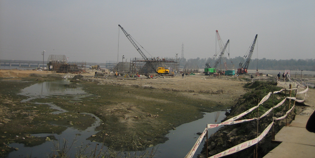
Apart from the tower foundations, which had to be designed for high vertical loads in combination with high horizontal seismic forces, the foundation for the back-stay pier was the most challenging. At this location there is a combination of steeply sloping and weathered rock, so a combination of well and pile foundations was developed. The uplift of up to 6,500t is mainly balanced by the weight of the wells and the connecting well cap which is 4.5m deep.
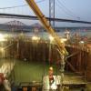
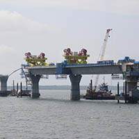
Construction of the well foundations was carried out using the jack down method, which offers savings in the quantities of concrete and steel required. This method also allows effective control during well sinking to avoid tilt and shift, for example when wells get stuck in stiff clay. The Yamuna River has not yet been dammed to form the lake and with the deck only approximately 12m above the ground, the usual free-cantilevering procedu