The most complex structural engineering procedure to be carried out on the UK’s Humber Bridge since it opened to traffic is currently under way on site, although drivers will not see much of it from deck level. The bearings that control the vertical and lateral position of the deck box girder at the towers are to be replaced under traffic in a year-long contract worth approximately US$6.3 million. In this major structural intervention, a new system of pendels and bearings, combined with wind shoes, will replace the A-frame rocker bearings at the ends of the deck box of the 1,410m-long main span.

Photo: Alastair Crompton
Contractor Spencer Group is implementing a system designed by consultant Arup, to resolve a problem which the owner Humber Bridge Board identified during routine inspections. The bridge in the east of England, which was the longest single-span suspension bridge in the world for 16 years after it opened in 1981, carries the A15 dual carriageway over the Humber estuary.
At each end of the side span and main span decks at the towers, pairs of A-frame rocker bearings connect the deck box to an 8m-deep portal beam of the tower. A-frames are also provided at the anchorage ends of the side span deck boxes. The A-frames resist both tension and compression axial vertical loading and are connected to the tower portal beam leg via preloaded bolts which link to a steel frame approximately 1m deep. Pairs of A-frames provide deck box torsional restraint; the cruciform cross-sections of the frames result in low plan torsion resistance, hence providing little restraint to deck end plan rotations.
The rocking motion of the A-frames allows the deck box free longitudinal movement. Routine inspections raised the capacity and performance of the main span A-frames as a potential issue. The A-frames on the main span at the north tower were found to have displaced vertically, a movement which was attributed to wear of the bearing pins and/or bearing casing.
Concern that the A-frames may not be free to rock, and hence could threaten the bridge articulation, led to the condition of A-frames at other locations being further investigated. If as suspected, the A-frames were seizing under live load, deck displacements would be accommodated by flexure of these units, which would be imposing severe fatigue loading on the A-frames. Given these concerns, it was decided to focus solely on the main span A-frame rockers, although the system proposed is also designed for future A-frame replacement on the side spans.
In 2011 a competitive tender to design a replacement system was won by consultant Arup. Specialist Eadon Consulting acted as subconsultant for mechanical engineering on the project, and the independent check was carried out by Aecom. Six options for a new system were developed but one stood out; replacement of the A-frames with pendels to take vertical loads and a wind shoe with opposed, preloaded sliding spherical bearings.
The vertical support reactions required at the tower, predominantly from forming a torsional reaction against traffic and wind loads, will be taken by rocking pendel bearings. This simplifies load transfer compared to the existing arrangement, and the pendels will be on the same centreline as the existing A-frames, offset 5.9m from the carriageway centreline to make best use of the existing internal deck steel arrangement and ensure the location of load application to the tower portal beam does not change. The pendels consist of a fabricated I-section with a bolted splice to aid installation; they will be subject to longitudinal deck displacements.
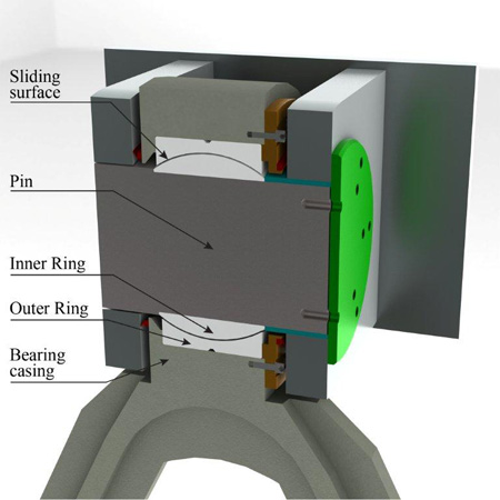
Spherical bearing mounted pin
Spherical bearing mounted pins manufactured to an approved design from a specialist bearing manufacturer are proposed instead of the existing bearings – these are more commonly used in mechanical engineering, and are used in products as wide-ranging as ship’s propeller shafts and car doors. The shaft – or in the case of the pendel, the bearing pin - sits inside a inner ring spherical element and the outer surface of the sphere bears on to a curved outer ring bearing surface. Relative movement between these two rings is allowed.
For the pendel application, the two surfaces will be specialist PTFE material, impregnated with lubricant to minimise the need for manual lubrication in service. The two elements that the bearing connects are fixed translationally, though they are free to rotate relative to one another about all axes. This allows for considerable flexibility in dealing with misalignment, ensuring the maximum possible bearing surface is in contact at all times. Such bearings are characterised by low wear and long design lives, but to accommodate the sphere and the low bearing pressures to ensure a pendel bearing design life of at least 50 years, the bearing pin required is much larger than the existing A-frames: 480mm compared to 250mm diameter.
Because the room available to house the bearing casing is limited, the design calls for the use of higher grade structural steels, S690QL1(-60) to BS EN 10025-6. Separating out the horizontal reaction required to resist wind forces into the wind shoe has a number of benefits, notably during construction and future replacement. Since lateral wind forces may be applied in either direction, not only from changes in wind direction but also due to dynamic effects, opposing bearings are required.
To prevent ingress of contaminants onto the bearing surface, the bearings will be preloaded such that a minimum bearing pressure of 2MPa is applied at all times. Two methods were considered to generate this pressure: either mechanically using disc springs or hydraulically using a cylinder. The ability to carefully control and monitor the preload that the hydraulic system offered, resulted in this detail being preferred. An arrangement using three independent units was developed: a hydraulic accumulator to provide pressurised oil; a hydraulic cylinder and a sliding spherical bearing.
Each of these units is relatively straightforward to procure both at construction and in the event of future replacement. The wind shoe will also be subject to longitudinal displacements, which would cause rapid wear to conventional PTFE sliding materials – such as has been seen on the Tsing Ma Bridge in Hong Kong.
Some bearing manufacturers now offer advanced self-lubricating bearing and sliding surface materials that claim bearing life in excess of 50km, and it is proposed to use such material in the wind shoe bearings. The wind shoe itself – which is a fabricated steel box - cantilevers from the deck box soffit and is offset from the carriageway centreline to avoid clashing with electrical and telecommunications cabling on the tower portal beam. In common with all steel attachments, site welding will be minimised to simplify quality control.
The new design only results in minor modifications to the load paths on the structure for the permanent case, but for the temporary case during construction, these changes are significant. Loads will be transferred to temporary pendels, outboard of the existing A-frames, and as a result the end deck box will be subject to higher loads. To avoid chasing the increased load effects back through the deck box and the wider s
